Network Topology#
A network topology in a broad sense describes the network design on physical and logical levels. Whether Clos, a Fat Tree or a Ring design, the topology is what inherently defines the network.
Just as an arbitrary topology is defined by its nodes and links, the network topology in EDA is modelled with the TopoNode and TopoLink resources. The EDA topology nodes are represented by the devices in your network, and the topology links define the connectivity between them.
If you have just completed the instructions in the Getting Started guide, recall the 3-node topology that the "Try EDA" setup comes with:
To represent this network topology in EDA you must create the TopoNode and TopoLink for each node and link in the network topology. Without network topology modelled with the respective topo resources, EDA cannot start managing the network devices.
The three-node topology in Getting Started is modelled with the TopoNode and TopoLink resources:
- For each device in the topology there is a corresponding
TopoNode - For each link between the nodes there is a corresponding
TopoLinkrepresenting the inter-switch connections - For each link from a node to an edge device (not shown in the diagram) there is a corresponding
TopoLinkrepresenting the edge connections.1
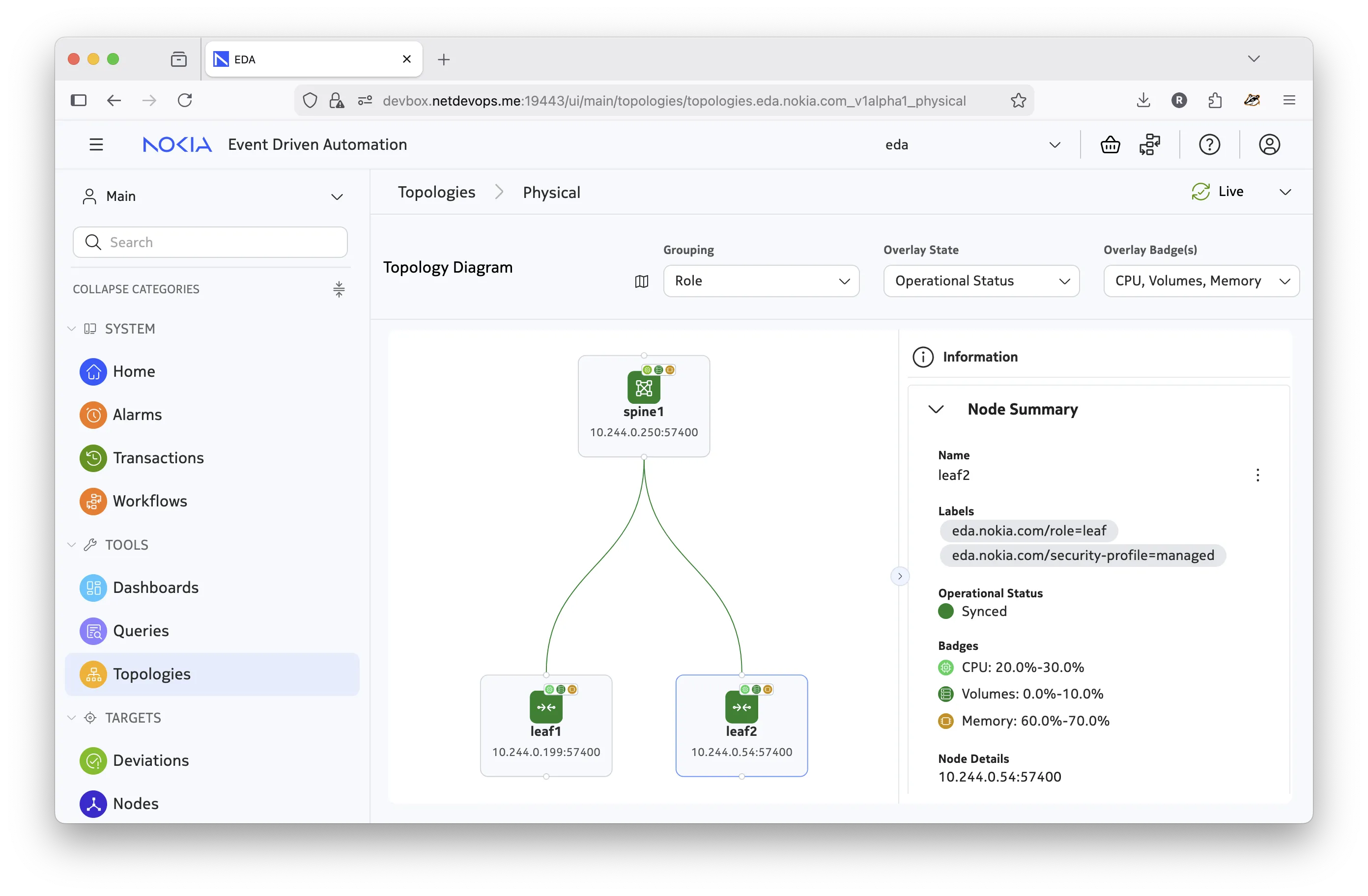
The following diagram illustrates how the topology resources represent the same network topology:
There is almost no difference with a physical topology. To see the topology diagram in the EDA UI select Topologies in the left-hand menu and click on the Physical row in the table of topologies:
Digital Twin topology
The Network Topology is used to model both the physical network and its matching Digital Twin. The Digital Twin topology (also known as the simulation topology) is covered in more detail on the Digital Twin page.
Viewing and working with network topologies in the EDA GUI is described in more detail on the Working with topology in the GUI page.
Topology resources#
The TopoNode and TopoLink resources in EDA make up the network topology that is used both by the real physical network and the Digital Twin. With the three-node topology created in the EDA cluster, you can see these resources in the EDA UI and using kubectl or edactl commands:
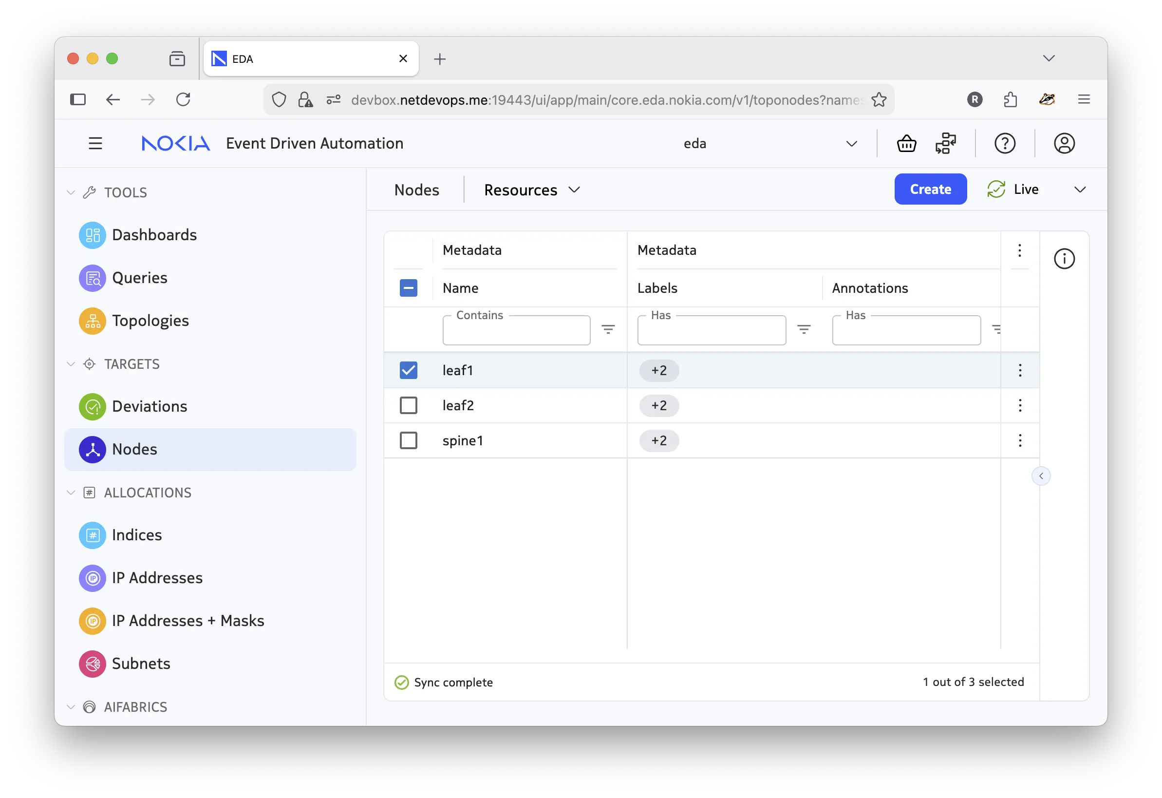
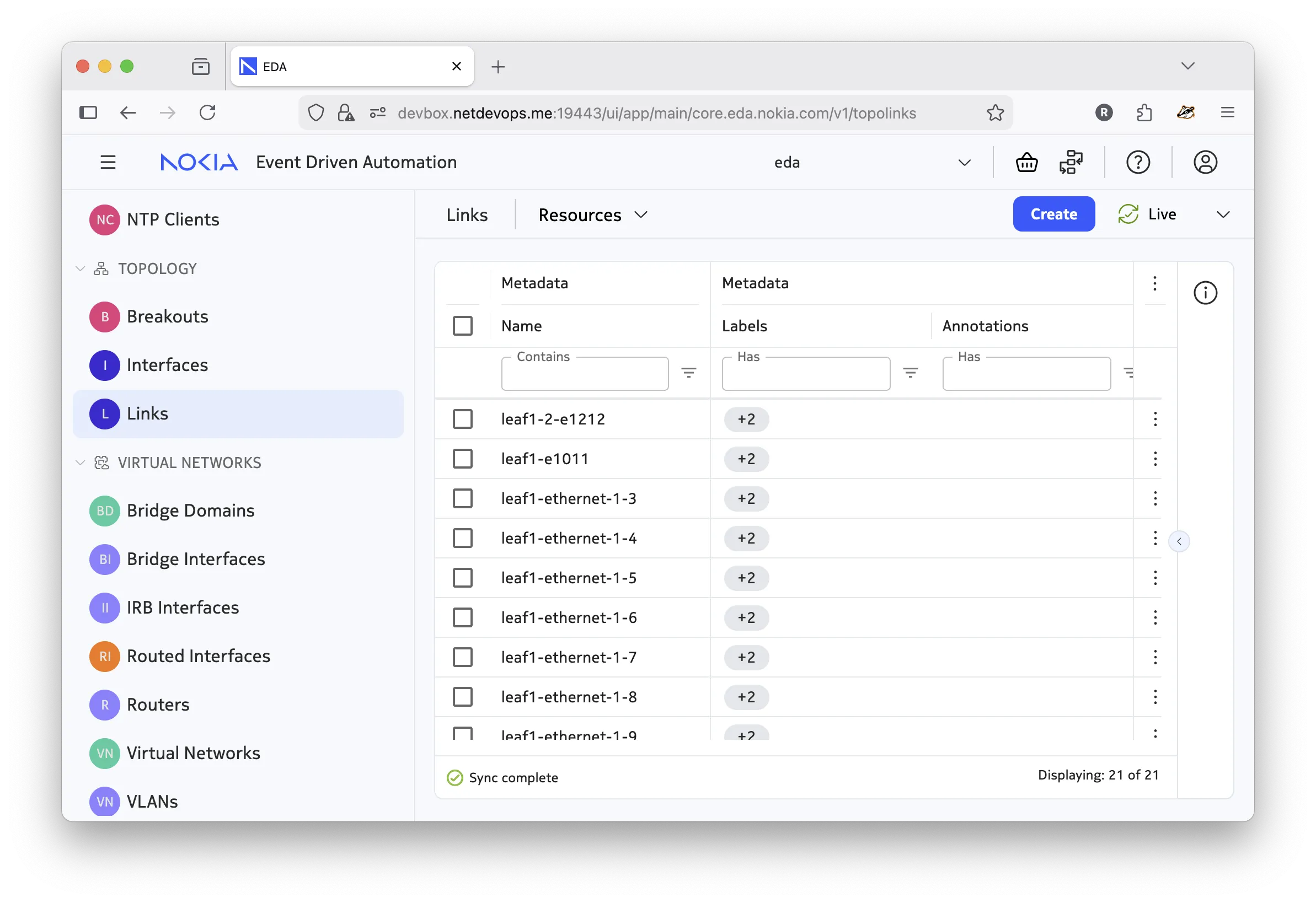
The TopoNode and TopoLink objects make up a topology. You can create these resources directly in the EDA UI, with the CLI tools, or using the API; but doing so can be tedious and error-prone as the number of nodes, and especially links, grows quickly.
To assist with the topology creation, EDA provides the Network Topology workflow - a workflow to define and deploy arbitrary topologies in a transactional manner.
Network topology workflow#
Instead of creating the topology resources individually, EDA provides a way to describe the topology via the Network Topology workflow that can be triggered using the UI, REST API, or via CLIs and applied in a single transaction.
A Workflow in EDA is a resource that defines a job or a set of jobs to be executed in a run-to-completion manner. A typical example of a workflow is the Image Upgrade workflow that performs the upgrade of a network device OS image.
Below is an example of a Network Topology Workflow resource, and how the Try EDA topology is defined with it:
apiVersion: topologies.eda.nokia.com/v1
kind: NetworkTopology
metadata:
  name: try-eda-topology
  namespace: eda
spec:
  operation: create  # operation to perform

  nodeTemplates: []     # list of node templates
  nodes: []             # list of nodes

  linkTemplates: []     # list of link templates
  links: []             # list of links

  simulation: {}        # digital twin topology settings
  checks: {}            # topology checks and dry runs
The three-node topology used in the Try EDA setup is defined with the following Network Topology workflow:
apiVersion: topologies.eda.nokia.com/v1alpha1
kind: NetworkTopology
metadata:
  name: try-eda-topology-a
  namespace: eda
spec:
  operation: replaceAll
  nodeTemplates:
    - name: leaf
      nodeProfile: srlinux-ghcr-25.10.1
      platform: 7220 IXR-D3L
      labels:
        eda.nokia.com/security-profile: managed
        eda.nokia.com/role: leaf
    - name: spine
      nodeProfile: srlinux-ghcr-25.10.1
      platform: 7220 IXR-D5
      labels:
        eda.nokia.com/security-profile: managed
        eda.nokia.com/role: spine
  nodes:
    - name: leaf1
      template: leaf
    - name: leaf2
      template: leaf
    - name: spine1
      template: spine
  linkTemplates:
    - name: isl
      type: interSwitch
      speed: 25G
      encapType: "null"
      labels:
        eda.nokia.com/role: interSwitch
    - name: edge
      type: edge
      encapType: dot1q
      labels:
        eda.nokia.com/role: edge
  links:
    ####################
    # ISLs
    ####################
    - name: leaf1-spine1-1
      template: isl
      endpoints:
        - local:
            node: leaf1
            interface: ethernet-1-1
          remote:
            node: spine1
            interface: ethernet-1-1
    - name: leaf1-spine1-2
      template: isl
      endpoints:
        - local:
            node: leaf1
            interface: ethernet-1-2
          remote:
            node: spine1
            interface: ethernet-1-2
    - name: leaf2-spine1-1
      template: isl
      endpoints:
        - local:
            node: leaf2
            interface: ethernet-1-1
          remote:
            node: spine1
            interface: ethernet-1-3
    - name: leaf2-spine1-2
      template: isl
      endpoints:
        - local:
            node: leaf2
            interface: ethernet-1-2
          remote:
            node: spine1
            interface: ethernet-1-4
    ####################
    # Edges
    ####################
    - name: leaf1-ethernet-1-3
      template: edge
      endpoints:
        - local:
            node: leaf1
            interface: ethernet-1-3
    - name: leaf1-ethernet-1-4
      template: edge
      endpoints:
        - local:
            node: leaf1
            interface: ethernet-1-4
    - name: leaf1-ethernet-1-5
      template: edge
      endpoints:
        - local:
            node: leaf1
            interface: ethernet-1-5
    - name: leaf1-ethernet-1-6
      template: edge
      endpoints:
        - local:
            node: leaf1
            interface: ethernet-1-6
    - name: leaf1-ethernet-1-7
      template: edge
      endpoints:
        - local:
            node: leaf1
            interface: ethernet-1-7
    - name: leaf1-ethernet-1-8
      template: edge
      endpoints:
        - local:
            node: leaf1
            interface: ethernet-1-8
    - name: leaf1-ethernet-1-9
      template: edge
      endpoints:
        - local:
            node: leaf1
            interface: ethernet-1-9
    - name: leaf1-e1011
      template: edge
      endpoints:
        - local:
            node: leaf1
            interface: ethernet-1-10
        - local:
            node: leaf1
            interface: ethernet-1-11
    - name: leaf2-ethernet-1-3
      template: edge
      endpoints:
        - local:
            node: leaf2
            interface: ethernet-1-3
    - name: leaf2-ethernet-1-4
      template: edge
      endpoints:
        - local:
            node: leaf2
            interface: ethernet-1-4
    - name: leaf2-ethernet-1-5
      template: edge
      endpoints:
        - local:
            node: leaf2
            interface: ethernet-1-5
    - name: leaf2-ethernet-1-6
      template: edge
      endpoints:
        - local:
            node: leaf2
            interface: ethernet-1-6
    - name: leaf2-ethernet-1-7
      template: edge
      endpoints:
        - local:
            node: leaf2
            interface: ethernet-1-7
    - name: leaf2-ethernet-1-8
      template: edge
      endpoints:
        - local:
            node: leaf2
            interface: ethernet-1-8
    - name: leaf2-ethernet-1-9
      template: edge
      endpoints:
        - local:
            node: leaf2
            interface: ethernet-1-9
    - name: leaf2-e1011
      template: edge
      endpoints:
        - local:
            node: leaf2
            interface: ethernet-1-10
        - local:
            node: leaf2
            interface: ethernet-1-11
    - name: leaf1-2-e1212
      template: edge
      endpoints:
        - local:
            node: leaf1
            interface: ethernet-1-12
        - local:
            node: leaf2
            interface: ethernet-1-12
  simulation:
    topology:
      - node: "*"
        interface: "*"
        simNode: testman-default
    simNodeTemplates:
      - name: default
        type: TestMan
    simNodes:
      - name: testman-default
        template: default
The structure shows that the Network Topology workflow resource spec uses the template-based approach to define nodes and links. Corresponding templates are defined in the nodeTemplates and linkTemplates sections, and then referenced in the nodes and links sections, respectively.
Using the template-based approach reduces repetition in the topology definition and lets you quickly change the common parameters in one place.
Note
This document does not dive into the details of the Digital Twin topology (simulation section). That topic is covered on the Digital Twin page.
Nodes#
To define the nodes, you create one or more templates and reference them in the nodes section. The values specified on the node level override the template values.
nodeTemplates:
  - name: leaf #(1)!
    nodeProfile: srlinux-ghcr-26.3.1 #(5)!
    platform: 7220 IXR-D3L #(4)!
    labels: #(2)!
      eda.nokia.com/security-profile: managed #(6)!
      eda.nokia.com/role: leaf

nodes:
  - name: leaf1 #(7)!
    template: leaf #(3)!
    labels:
      new-node-level-label: new-value #(8)!
- The free-form name of the node template resource.
- The labels to be applied to the node.
- The name of the node template that this node is based on.
- Platform name.
NPP and Bootstrap server validate the platform name they see upon connection. - Node profile.
A reference to aNodeProfileresource that defines the profile of the node. - A label that is used by the
NodeSecurityProfileresource to determine the security profile of the node. - The name of the node.
- Parameters specified on the node level override/merge with the template values. In this case, a new label is merged with the template-level labels.
Based on the provided node definition, EDA will create the respective TopoNode resource representing the node in the topology.
apiVersion: core.eda.nokia.com/v1
kind: TopoNode
metadata:
  labels:
    eda.nokia.com/role: leaf
    eda.nokia.com/security-profile: managed
    new-node-level-label: new-value
  name: leaf1
  namespace: eda
spec:
  nodeProfile: srlinux-ghcr-26.3.1
  npp:
    mode: normal
  onBoarded: true
  operatingSystem: srl
  platform: 7220 IXR-D3L
  productionAddress: {}
  version: 26.3.1
status:
  node-details: 10.244.0.224:57400
  node-state: Synced
  npp-details: 10.244.0.75:50057
  npp-pod: eda-npp-1
  npp-state: Connected
  operatingSystem: srl
  platform: 7220 IXR-D3L
  simulate: true
  version: 26.3.1
Links#
A link represents a connection between two nodes in the topology. In EDA, you will find two link types used in the context of a network topology:
- interSwitch - a link between two topology nodes, typically representing a connection between two network devices.
- edge - a link connecting a topology node to an edge device that is not part of the topology. Most often the access links from the leaf switches to the end devices (servers, workstations, etc.) are modelled as edge links.
To define the links, create one or more link templates and reference them in the links section. The values specified on the link level override the template values.
The following examples show common topology link definitions that you will find in the Network Topology workflow spec:
An inter switch link (ISL) is a point-to-point link that connects two network devices in the topology. In the example below, the ISL connects leaf1 and spine1 nodes using their ethernet-1-1 interfaces.
Diagram
linkTemplates:
  - name: isl #(6)!
    type: interSwitch #(5)!
    speed: 25G #(7)!
    encapType: "null"
    labels: #(2)!
      eda.nokia.com/role: interSwitch

links:
  - name: leaf1-spine1-1 #(1)!
    template: isl #(9)!
    endpoints: #(8)!
      - local: #(3)!
          node: leaf1
          interface: ethernet-1-1
        remote: #(4)!
          node: spine1
          interface: ethernet-1-1
- The name of the
TopoLinkresource. - The labels to be applied to the node.
- Definition of Local, or "A" endpoint of the link. Can contain the following fields:
interface- Normalized name of the interface/port, e.g.ethernet-1-1.
node- The reference to theTopoNoderesource that this side of a link is connected to. - Definition of Remote, or "B" endpoint of the link. Contains the same fields as the
localdefinition. - The type of link. One of
edge,interSwitch,loopback - Name of the link template.
- Default link speed. Optional.
- Endpoints is a list of endpoint definitions, where each endpoint object contains the
localand optionally theremotesides.
For a typical inter-switch link bothlocalandremotesides are defined, where thelocalside refers to one topology node and theremoteside refers to another.
You will see how edge links don't have aremoteside defined in the next example. - Reference to the link template that this link is based on.
As a result of this link definition, EDA creates two resources: a TopoLink resource representing the link itself, and two Interface resources representing the interfaces on both ends of the link. The Interface resources is responsible for configuring the respective interfaces on the devices.
apiVersion: core.eda.nokia.com/v1
kind: TopoLink
metadata:
  labels:
    eda.nokia.com/role: interSwitch
    eda.nokia.com/source-link: leaf1-spine1-1
  name: leaf1-spine1-1
  namespace: eda
spec:
  links:
    - local:
        interface: ethernet-1-1
        interfaceResource: leaf1-ethernet-1-1
        node: leaf1
      remote:
        interface: ethernet-1-1
        interfaceResource: spine1-ethernet-1-1
        node: spine1
      speed: 25G
      type: interSwitch
status:
  members:
    - interface: ethernet-1-1
      node: leaf1
      operationalState: up
    - interface: ethernet-1-1
      node: spine1
      operationalState: up
  operationalState: up
apiVersion: interfaces.eda.nokia.com/v1alpha1
kind: Interface
metadata:
  labels:
    eda.nokia.com/role: interSwitch
    eda.nokia.com/source-link: leaf1-spine1-1
  name: leaf1-ethernet-1-1
  namespace: eda
spec:
  enabled: true
  encapType: 'null'
  ethernet:
    stormControl: {}
  lldp: true
  members:
    - enabled: true
      interface: ethernet-1-1
      lacpPortPriority: 32768
      node: leaf1
  type: interface
status:
  enabled: true
  lastChange: '2025-11-28T12:08:22.671Z'
  members:
    - enabled: true
      interface: ethernet-1-1
      lastChange: '2025-11-28T12:08:22.671Z'
      neighbors:
        - interface: ethernet-1/1
          node: spine1
      node: leaf1
      nodeInterface: ethernet-1/1
      operationalState: up
      speed: 100G
  operationalState: up
  speed: 100G
apiVersion: interfaces.eda.nokia.com/v1alpha1
kind: Interface
metadata:
  labels:
    eda.nokia.com/role: interSwitch
    eda.nokia.com/source-link: leaf1-spine1-1
  name: spine1-ethernet-1-1
  namespace: eda
spec:
  enabled: true
  encapType: 'null'
  ethernet:
    stormControl: {}
  lldp: true
  members:
    - enabled: true
      interface: ethernet-1-1
      lacpPortPriority: 32768
      node: spine1
  type: interface
status:
  enabled: true
  lastChange: '2025-11-28T12:08:22.667Z'
  members:
    - enabled: true
      interface: ethernet-1-1
      lastChange: '2025-11-28T12:08:22.667Z'
      neighbors:
        - interface: ethernet-1/1
          node: leaf1
      node: spine1
      nodeInterface: ethernet-1/1
      operationalState: up
      speed: 400G
  operationalState: up
  speed: 400G
The edge link is a link that connects a topology node (typically a leaf switch) to an edge device that is not part of the topology. The edge device may be a server, a GPU, or a generic device that is not managed by EDA. As this link has only one side connected to a topology node, only the local side is defined in the link definition:
Diagram
linkTemplates:
  - name: edge
    type: edge #(1)!
    encapType: dot1q
    labels:
      eda.nokia.com/role: edge #(2)!

links:
  - name: leaf1-ethernet-1-3
    template: edge
    endpoints:
      - local:
          node: leaf1
          interface: ethernet-1-3
- Edge links have their own special type:
edge. - The label is optional, but since the edge links are targeted by the overlay services like Virtual Network, you should label them accordingly so that applications can easily select the edge links.
As a result of this link definition, EDA will create two resources: a TopoLink resource representing the link itself, and the Interface resource representing the interfaces on the leaf side. The Interface resources will be responsible for configuring the respective interface on the leaf device.
apiVersion: core.eda.nokia.com/v1
kind: TopoLink
metadata:
  labels:
    eda.nokia.com/role: edge
    eda.nokia.com/source-link: leaf2-ethernet-1-3
  name: leaf2-ethernet-1-3
  namespace: eda
spec:
  links:
    - local:
        interface: ethernet-1-3
        interfaceResource: leaf2-ethernet-1-3
        node: leaf2
      remote:
        interfaceResource: ''
        node: ''
      type: edge
status:
  members:
    - interface: ethernet-1-3
      node: leaf2
      operationalState: up
  operationalState: up
apiVersion: interfaces.eda.nokia.com/v1alpha1
kind: Interface
metadata:
  labels:
    eda.nokia.com/role: edge
    eda.nokia.com/source-link: leaf1-ethernet-1-3
  name: leaf1-ethernet-1-3
  namespace: eda
spec:
  enabled: true
  encapType: dot1q
  ethernet:
    stormControl: {}
  lldp: true
  members:
    - enabled: true
      interface: ethernet-1-3
      lacpPortPriority: 32768
      node: leaf1
  type: interface
status:
  enabled: true
  lastChange: '2025-11-28T12:08:22.795Z'
  members:
    - enabled: true
      interface: ethernet-1-3
      lastChange: '2025-11-28T12:08:22.795Z'
      neighbors: []
      node: leaf1
      nodeInterface: ethernet-1/3
      operationalState: up
      speed: 100G
  operationalState: up
  speed: 100G
The Link Aggregation Group (LAG) link combines multiple physical interfaces into a single logical link. In EDA, two types of LAG exist: local LAG and multihomed LAG.
The "local" LAG aggregates ports between a single pair of nodes, and is created by specifying multiple endpoints each having only local sides defined on the same node. In the example below, the LAG consists of ethernet-1-10 and ethernet-1-11 interfaces on the leaf1 node reaching out to an edge device that is expected to have a matching LAG configuration.
Diagram
linkTemplates:
  - name: edge
    type: edge
    encapType: dot1q
    labels:
      eda.nokia.com/role: edge

links:
  - name: leaf1-e1011
    template: edge
    endpoints:
      - local:
          node: leaf1 #(1)!
          interface: ethernet-1-10
      - local:
          node: leaf1
          interface: ethernet-1-11
- Both endpoints in this example refer to the same node:
leaf1. This indicates that this is a local LAG link, in which both interfaces belong to the same node.
As a result of this link definition, EDA creates two resources: a TopoLink resource representing the link itself, and only one Interface resource with two members in it, representing the local LAG.
Also, note that the Interface resource features LAG-specific configuration under the lag section in its spec.
apiVersion: core.eda.nokia.com/v1
kind: TopoLink
metadata:
  labels:
    eda.nokia.com/role: edge
    eda.nokia.com/source-link: leaf1-e1011
  name: leaf1-e1011
  namespace: eda
spec:
  links:
    - local:
        interface: ethernet-1-10
        interfaceResource: lag-leaf1-e1011-local
        node: leaf1
      remote:
        interfaceResource: ''
        node: ''
      type: edge
    - local:
        interface: ethernet-1-11
        interfaceResource: lag-leaf1-e1011-local
        node: leaf1
      remote:
        interfaceResource: ''
        node: ''
      type: edge
status:
  members:
    - interface: ethernet-1-10
      node: leaf1
      operationalState: up
    - interface: ethernet-1-11
      node: leaf1
      operationalState: up
  operationalState: up
apiVersion: interfaces.eda.nokia.com/v1alpha1
kind: Interface
metadata:
  labels:
    eda.nokia.com/role: edge
    eda.nokia.com/source-link: leaf1-e1011
  name: lag-leaf1-e1011-local
  namespace: eda
spec:
  enabled: true
  encapType: dot1q
  ethernet:
    stormControl: {}
  lag:
    lacp:
      interval: fast
      lacpFallback:
        mode: static
        timeout: 60
      mode: active
      systemPriority: 32768
    minLinks: 1
    multihoming:
      esi: auto
      mode: all-active
      reloadDelayTimer: 100
      revertive: false
    type: lacp
  lldp: true
  members:
    - enabled: true
      interface: ethernet-1-10
      lacpPortPriority: 32768
      node: leaf1
    - enabled: true
      interface: ethernet-1-11
      lacpPortPriority: 32768
      node: leaf1
  type: lag
status:
  enabled: true
  lag:
    adminKey: 2
    systemIdMac: FE:2F:AA:00:00:02
  lastChange: '2025-11-28T12:08:25.692Z'
  members:
    - enabled: true
      interface: ethernet-1-10
      lastChange: '2025-11-28T12:08:25.674Z'
      neighbors: []
      node: leaf1
      nodeInterface: ethernet-1/10
      operationalState: up
      speed: 100G
    - enabled: true
      interface: ethernet-1-11
      lastChange: '2025-11-28T12:08:25.692Z'
      neighbors: []
      node: leaf1
      nodeInterface: ethernet-1/11
      operationalState: up
      speed: 100G
    - enabled: true
      interface: lag-2
      lastChange: '2025-11-28T12:08:25.675Z'
      neighbors: []
      node: leaf1
      nodeInterface: lag2
      operationalState: up
      speed: 200G
  operationalState: up
  speed: 200G
In contrast to a local LAG, the multihome LAG aggregates ports from a single node towards two and more nodes. A typical application for a multihome LAG is the ESI LAG in EVPN deployments where up to four switches connect to the same downstream device (for example, a server or a router) using a LAG.
You create a multihome LAG by specifying multiple endpoints each having only local sides defined for different nodes. In the example below, the multihome LAG consists of ethernet-1-12 on the leaf1 and the same ethernet-1-12 on the leaf2 node.
Diagram
linkTemplates:
  - name: edge
    type: edge
    encapType: dot1q
    labels:
      eda.nokia.com/role: edge

links:
  - name: leaf1-2-e1212
    template: edge
    endpoints:
      - local:
          node: leaf1 #(1)!
          interface: ethernet-1-12
      - local:
          node: leaf2
          interface: ethernet-1-12
- In contrast to the local LAG example, here the
localsides of the endpoint object refer to different nodes -leaf1andleaf2. This denotes the "multihome" nature of this LAG link.
As a result of this link definition, EDA will create two resources - a TopoLink resource representing the link itself, and only one Interface resource with two members, where each member belongs to a different node.
Also, note that the Interface resource features LAG-specific configuration under the lag section in its spec.
apiVersion: core.eda.nokia.com/v1
kind: TopoLink
metadata:
  labels:
    eda.nokia.com/role: edge
    eda.nokia.com/source-link: leaf1-2-e1212
  name: leaf1-2-e1212
  namespace: eda
spec:
  links:
    - local:
        interface: ethernet-1-12
        interfaceResource: lag-leaf1-2-e1212-local
        node: leaf1
      remote:
        interfaceResource: ''
        node: ''
      type: edge
    - local:
        interface: ethernet-1-12
        interfaceResource: lag-leaf1-2-e1212-local
        node: leaf2
      remote:
        interfaceResource: ''
        node: ''
      type: edge
status:
  members:
    - interface: ethernet-1-12
      node: leaf1
      operationalState: up
    - interface: ethernet-1-12
      node: leaf2
      operationalState: up
  operationalState: up
apiVersion: interfaces.eda.nokia.com/v1alpha1
kind: Interface
metadata:
  labels:
    eda.nokia.com/role: edge
    eda.nokia.com/source-link: leaf1-2-e1212
  name: lag-leaf1-2-e1212-local
  namespace: eda
spec:
  enabled: true
  encapType: dot1q
  ethernet:
    stormControl: {}
  lag:
    lacp:
      interval: fast
      lacpFallback:
        mode: static
        timeout: 60
      mode: active
      systemPriority: 32768
    minLinks: 1
    multihoming:
      esi: auto
      mode: all-active
      reloadDelayTimer: 100
      revertive: false
    type: lacp
  lldp: true
  members:
    - enabled: true
      interface: ethernet-1-12
      lacpPortPriority: 32768
      node: leaf1
    - enabled: true
      interface: ethernet-1-12
      lacpPortPriority: 32768
      node: leaf2
  type: lag
status:
  enabled: true
  lag:
    adminKey: 3
    systemIdMac: FE:2F:AA:00:00:03
  lastChange: '2025-11-28T12:08:27.578Z'
  members:
    - enabled: true
      interface: ethernet-1-12
      lastChange: '2025-11-28T12:08:25.697Z'
      neighbors: []
      node: leaf1
      nodeInterface: ethernet-1/12
      operationalState: up
      speed: 100G
    - enabled: true
      interface: lag-1
      lastChange: '2025-11-28T12:08:25.697Z'
      neighbors: []
      node: leaf1
      nodeInterface: lag1
      operationalState: up
      speed: 100G
    - enabled: true
      interface: ethernet-1-12
      lastChange: '2025-11-28T12:08:27.577Z'
      neighbors: []
      node: leaf2
      nodeInterface: ethernet-1/12
      operationalState: up
      speed: 100G
    - enabled: true
      interface: lag-2
      lastChange: '2025-11-28T12:08:27.578Z'
      neighbors: []
      node: leaf2
      nodeInterface: lag2
      operationalState: up
      speed: 100G
  operationalState: up
  speed: 100G
Breakouts#
Breakouts allow you to split a high-speed interface into multiple lower-speed channels. For example, a 400G port on Nokia SR Linux 7220 IXR-H4 can be broken out into multiple lower speed interfaces; for example, 4 by 100G. You enable port breakouts with the Breakout resource, which you can provide in the Network Topology workflow's link template section.
While the Try EDA three-node topology does not use breakout ports, the example below takes a similar topology with two leafs and one spine, where the ethernet-1-1 interface on spine1 is broken down into four 100G interfaces to which the leafs connect.
While the "Try EDA 3-node topology" does not use breakout ports, the example below will take a similar topology with two leafs and one spine, where the ethernet-1-1 interface on spine1 is broken down into four 100G interfaces to which the leafs connect.
To capture the intent of using a breakout port on spine1, use the ISL link template and specify the breakout port in the breakouts section, as shown below:
linkTemplates:
  - name: isl
    labels:
      eda.nokia.com/role: interSwitch
    type: interSwitch
    breakouts:
      - remote: #(1)!
          channels: 4
          speed: 100G
- Remote side of this ISL uses breakout 4x100G
The isl link template contains the breakouts section that specifies the breakout port configuration to use on the remote side of the link that uses this template.
The links can then use the isl link template to define the inter-switch connections between the leaf and spine nodes as usual. However, because the remote side of the link is now a breakout port, the interface name on the remote side must include the channel suffix: ethernet-1-1-1, ethernet-1-1-2, etc.
links:
  - name: leaf1-spine1-1
    template: isl
    endpoints:
      - local:
          node: leaf1
          interface: ethernet-1-1
        remote:
          node: spine1
          interface: ethernet-1-1-1 #(1)!
  - name: leaf1-spine1-2
    template: isl
    endpoints:
      - local:
          node: leaf1
          interface: ethernet-1-2
        remote:
          node: spine1
          interface: ethernet-1-1-2
  - name: leaf2-spine1-1
    template: isl
    endpoints:
      - local:
          node: leaf2
          interface: ethernet-1-1
        remote:
          node: spine1
          interface: ethernet-1-1-3
  - name: leaf2-spine1-2
    template: isl
    endpoints:
      - local:
          node: leaf2
          interface: ethernet-1-2
        remote:
          node: spine1
          interface: ethernet-1-1-4
- Note that the interface name of a remote port that uses the breakout is represented in a normalized way with its channel suffix,
ethernet-1-1-1,ethernet-1-1-2, denoting the channel index.
Because the link template specifies the breakout only on a remote side of a link, the remote endpoint uses the breakout notation. The link template may include breakouts on local, remote, or both sides.
The breakout definition shown above creates the Breakout resource that can be seen in the Topology > Breakouts section of the EDA UI.
apiVersion: interfaces.eda.nokia.com/v1
kind: Breakout
metadata:
  name: breakouts
  namespace: breakout-test
spec:
  channels: 4
  interfaces:
    - ethernet-1-1
  nodes:
    - spine1
  speed: 100G
The Breakout resource is responsible for configuring the breakout port on the specified nodes and interfaces.
Topology operations#
Network Topology is a Workflow resource. You can trigger it using any of the EDA interfaces: UI, API, or CLI.
Regardless of the interface you choose to create the Network Topology resource, you need to populate the Network Topology resources and select the desired operation: reconcile, create, replace/replaceAll, or delete/deleteAll.
To demonstrate the behavior of each operation, create a net-topo-test namespace and use it to deploy the topology following the examples below.
- If you don't have
edactlinstalled, install it with a single command.
Create#
To create a Network Topology, select the Create operation in the Network Topology workflow spec. The Create operation generates an error if any of the topology resources already exist in the target namespace; therefore, it is suitable for either creating a new topology in an empty namespace, or adding new nodes and links to an existing topology without modifying the existing resources.
Workflow names
Workflow resources should have unique names within a namespace. When creating a new workflow in EDA UI the name is auto-generated, and when using kubectl users can leverage Kubernetes' generateName feature to create unique names. In the examples below, use the generateName field with kubectl snippets instead of providing a fixed name.
Since the new net-topo-test namespace is empty, you safely create the topology there using the following workflow:
apiVersion: topologies.eda.nokia.com/v1alpha1
kind: NetworkTopology
metadata:
  generateName: create- #(1)!
  namespace: net-topo-test
spec:
  operation: create

  nodeTemplates:
    - name: node
      nodeProfile: srlinux-ghcr-25.10.1
      platform: 7220 IXR-D3L
      labels:
        eda.nokia.com/security-profile: managed
  nodes:
    - name: node1
      template: node
    - name: node2
      template: node

  linkTemplates:
    - name: isl
      type: interSwitch
  links:
    - name: node1-node2
      template: isl
      endpoints:
        - local:
            node: node1
            interface: ethernet-1-1
          remote:
            node: node2
            interface: ethernet-1-1
- The
generateNamefield lets Kubernetes generate a unique name for the workflow resource, and is only applicable for cases when the workflow resource is created withkubectl. When pasting this snippet in the EDA UI, replace this field with thename: some-unique-namefield.
cat << 'EOF' | kubectl create -f -
apiVersion: topologies.eda.nokia.com/v1alpha1
kind: NetworkTopology
metadata:
  generateName: create- #(1)!
  namespace: net-topo-test
spec:
  operation: create

  nodeTemplates:
    - name: node
      nodeProfile: srlinux-ghcr-25.10.1
      platform: 7220 IXR-D3L
      labels:
        eda.nokia.com/security-profile: managed
  nodes:
    - name: node1
      template: node
    - name: node2
      template: node

  linkTemplates:
    - name: isl
      type: interSwitch
  links:
    - name: node1-node2
      template: isl
      endpoints:
        - local:
            node: node1
            interface: ethernet-1-1
          remote:
            node: node2
            interface: ethernet-1-1

EOF
You should expect the workflow created for this topology to create two nodes and one link in the net-topo-test namespace.
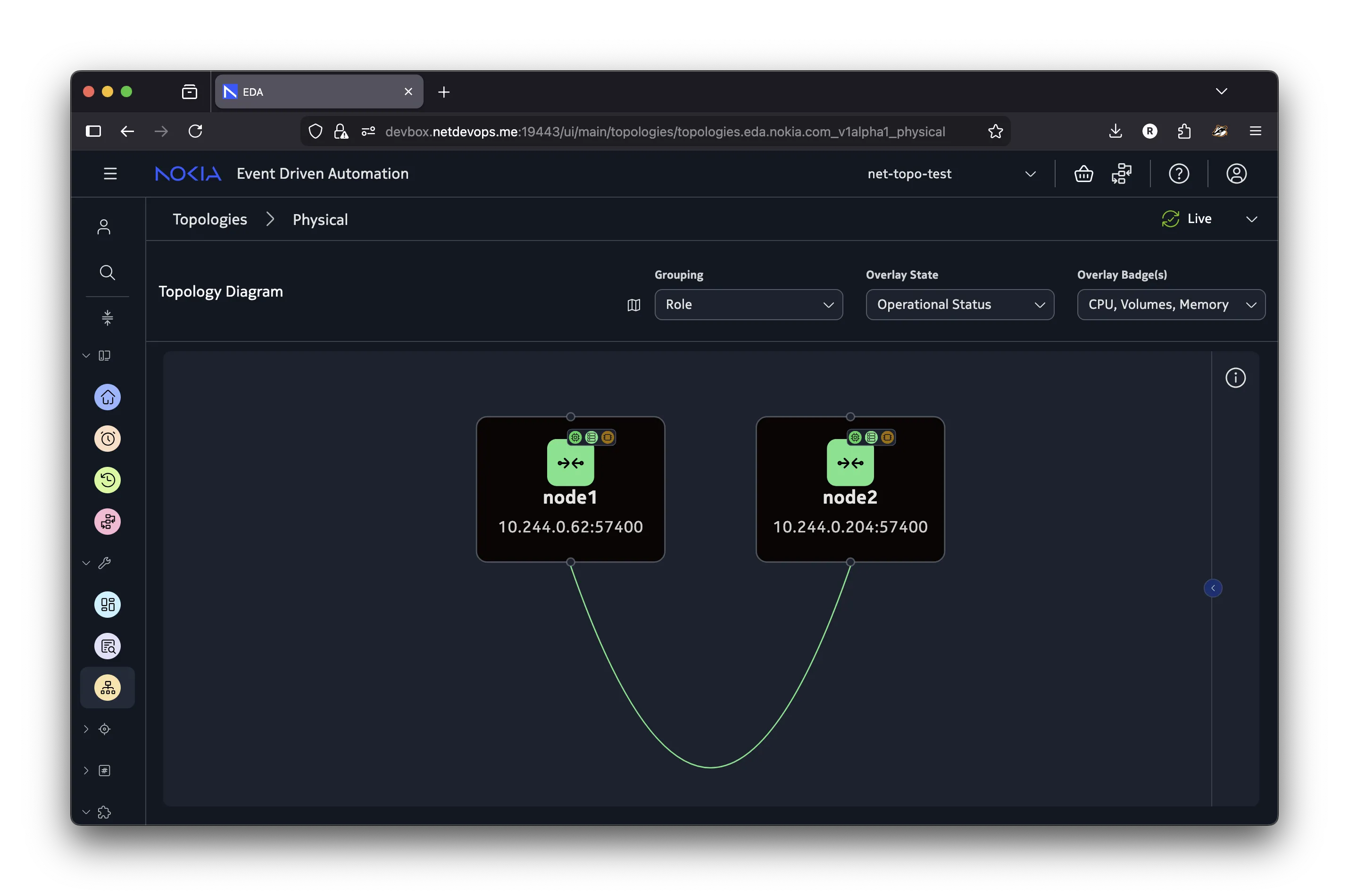
The
Createoperation fails if any of the topology resources provided in the spec already exist in the target namespace.
Because the Create operation adds new topology resources without modifying the existing ones, you can use it to incrementally add new nodes and links to a topology. For example, to add a new node node3 and connect it to node1, create a new workflow with the Create operation and provide only the new node and its links in the spec.
apiVersion: topologies.eda.nokia.com/v1alpha1
kind: NetworkTopology
metadata:
  generateName: add-
  namespace: net-topo-test
spec:
  operation: create

  nodeTemplates:
    - name: node
      nodeProfile: srlinux-ghcr-25.10.1
      platform: 7220 IXR-D3L
      labels:
        eda.nokia.com/security-profile: managed
  nodes:
    - name: node3
      template: node

  linkTemplates:
    - name: isl
      type: interSwitch
  links:
    - name: node1-node3
      template: isl
      endpoints:
        - local:
            node: node1
            interface: ethernet-1-2
          remote:
            node: node3
            interface: ethernet-1-1
cat << 'EOF' | kubectl create -f -
apiVersion: topologies.eda.nokia.com/v1alpha1
kind: NetworkTopology
metadata:
  generateName: add-
  namespace: net-topo-test
spec:
  operation: create

  nodeTemplates:
    - name: node
      nodeProfile: srlinux-ghcr-25.10.1
      platform: 7220 IXR-D3L
      labels:
        eda.nokia.com/security-profile: managed
  nodes:
    - name: node3
      template: node

  linkTemplates:
    - name: isl
      type: interSwitch
  links:
    - name: node1-node3
      template: isl
      endpoints:
        - local:
            node: node1
            interface: ethernet-1-2
          remote:
            node: node3
            interface: ethernet-1-1

EOF
The result of running this workflow will be that node3 is added to the existing topology along with its link to node1, while node1 and node2 remain unchanged.
Reconcile#
Use the Reconcile operation to reconcile the existing topology with the desired one. It compares the existing topology with the desired one and makes the necessary changes to the existing topology to bring it to the desired state. The important difference between the Reconcile and Create operations is that the Reconcile operation does not generate an error if any of the topology resources do not exist in the target namespace, but will instead create them to match the desired topology.
The Reconcile operation is suitable for both creating a new topology in an empty namespace, and adding new nodes and links to an existing topology without modifying the existing resources. However, it requires that you provide the full desired topology definition in the spec.
To have a topology with just node1 and node3, with the label reconcile: test added to both nodes and one more link between them, create a specification like the example below:
apiVersion: topologies.eda.nokia.com/v1alpha1
kind: NetworkTopology
metadata:
  generateName: reconcile-
  namespace: net-topo-test
spec:
  operation: reconcile

  nodeTemplates:
    - name: node
      nodeProfile: srlinux-ghcr-25.10.1
      platform: 7220 IXR-D3L
      labels:
        eda.nokia.com/security-profile: managed
        reconcile: test
  nodes:
    - name: node1
      template: node
    - name: node3
      template: node

  linkTemplates:
    - name: isl
      type: interSwitch
  links:
    - name: node1-node3
      template: isl
      endpoints:
        - local:
            node: node1
            interface: ethernet-1-2
          remote:
            node: node3
            interface: ethernet-1-1
    - name: node1-node3-2
      template: isl
      endpoints:
        - local:
            node: node1
            interface: ethernet-1-1
          remote:
            node: node3
            interface: ethernet-1-2
cat << 'EOF' | kubectl create -f -
apiVersion: topologies.eda.nokia.com/v1alpha1
kind: NetworkTopology
metadata:
  generateName: reconcile-
  namespace: net-topo-test
spec:
  operation: reconcile

  nodeTemplates:
    - name: node
      nodeProfile: srlinux-ghcr-25.10.1
      platform: 7220 IXR-D3L
      labels:
        eda.nokia.com/security-profile: managed
        reconcile: test
  nodes:
    - name: node1
      template: node
    - name: node3
      template: node

  linkTemplates:
    - name: isl
      type: interSwitch
  links:
    - name: node1-node3
      template: isl
      endpoints:
        - local:
            node: node1
            interface: ethernet-1-2
          remote:
            node: node3
            interface: ethernet-1-1
    - name: node1-node3-2
      template: isl
      endpoints:
        - local:
            node: node1
            interface: ethernet-1-1
          remote:
            node: node3
            interface: ethernet-1-2

EOF
The outcomes of this workflow will be:
node1andnode3is not re-created, because they already exist in the target namespace- label
reconcile: testis added to both nodes - an existing link between
node1andnode3remains unchanged - a new link between
node1andnode3is created to connectnode1tonode3 node2is removed from the topology along with its link tonode1node1andnode3briefly move to theOnboarded: falsestate, and NPPs reconnect to the nodes shortly after the workflow completes.
Replace#
Use the Replace operation to replace the existing topology with a new one. It comes in two variants: replace and replaceAll.
When using the replace operation, the workflow only replaces the existing topology resources whose names match the ones defined in the workflow spec. Topology resources that exist in the target namespace but are not part of the new topology definition are left unmodified. The example below demonstrates changing the node2 definition by adding the node-level platform value, overriding the template. The result of this replace operation is that node1 remains unchanged, but node2 has its platform set to 7220 IXR-D2L.
apiVersion: topologies.eda.nokia.com/v1alpha1
kind: NetworkTopology
metadata:
  generateName: replace-
  namespace: net-topo-test
spec:
  operation: replace

  nodeTemplates:
    - name: node
      nodeProfile: srlinux-ghcr-25.10.1
      platform: 7220 IXR-D3L
      labels:
        eda.nokia.com/security-profile: managed
  nodes:
    - name: node1
      template: node
    - name: node2
      template: node
      platform: 7220 IXR-D2L

  linkTemplates:
    - name: isl
      type: interSwitch
  links:
    - name: node1-node2
      template: isl
      endpoints:
        - local:
            node: node1
            interface: ethernet-1-1
          remote:
            node: node2
            interface: ethernet-1-1
cat << 'EOF' | kubectl create -f -
apiVersion: topologies.eda.nokia.com/v1alpha1
kind: NetworkTopology
metadata:
  generateName: replace-
  namespace: net-topo-test
spec:
  operation: replace

  nodeTemplates:
    - name: node
      nodeProfile: srlinux-ghcr-25.10.1
      platform: 7220 IXR-D3L
      labels:
        eda.nokia.com/security-profile: managed
  nodes:
    - name: node1
      template: node
    - name: node2
      template: node
      platform: 7220 IXR-D2L

  linkTemplates:
    - name: isl
      type: interSwitch
  links:
    - name: node1-node2
      template: isl
      endpoints:
        - local:
            node: node1
            interface: ethernet-1-1
          remote:
            node: node2
            interface: ethernet-1-1

EOF
Changing node-specific parameters like platform, operating system, version, etc. triggers re-onboarding of the node.
When using the replaceAll operation, the workflow first removes all of the topology resources from the targeted namespace and then adds the resources defined in the workflow spec. This operation is useful when you want to completely replace the existing topology with a new one.
Danger
Running the workflow with the replaceAll operation effectively deletes all of the topology resources in the target namespace and creates the new node and link objects as defined in the workflow spec. Use this with caution to avoid unintentional topology changes.
The example below demonstrates how the previous topology with node1 and node2 is replaced with a new topology that consists of the three nodes, switch1, switch2, and switch3, and two links connecting them. The names of the nodes are different, but this is not a problem because the replaceAll operation removes all previous nodes and links and replaces them with the new ones.
apiVersion: topologies.eda.nokia.com/v1alpha1
kind: NetworkTopology
metadata:
  generateName: replace-all-
  namespace: net-topo-test
spec:
  operation: replaceAll

  nodeTemplates:
    - name: node
      nodeProfile: srlinux-ghcr-25.10.1
      platform: 7220 IXR-D3L
      labels:
        eda.nokia.com/security-profile: managed
  nodes:
    - name: switch1
      template: node
    - name: switch2
      template: node
    - name: switch3
      template: node

  linkTemplates:
    - name: isl
      type: interSwitch
  links:
    - name: switch1-switch2
      template: isl
      endpoints:
        - local:
            node: switch1
            interface: ethernet-1-1
          remote:
            node: switch2
            interface: ethernet-1-1
    - name: switch1-switch3
      template: isl
      endpoints:
        - local:
            node: switch1
            interface: ethernet-1-2
          remote:
            node: switch3
            interface: ethernet-1-1
cat << 'EOF' | kubectl create -f -
apiVersion: topologies.eda.nokia.com/v1alpha1
kind: NetworkTopology
metadata:
  generateName: replace-all-
  namespace: net-topo-test
spec:
  operation: replaceAll

  nodeTemplates:
    - name: node
      nodeProfile: srlinux-ghcr-25.10.1
      platform: 7220 IXR-D3L
      labels:
        eda.nokia.com/security-profile: managed
  nodes:
    - name: switch1
      template: node
    - name: switch2
      template: node
    - name: switch3
      template: node

  linkTemplates:
    - name: isl
      type: interSwitch
  links:
    - name: switch1-switch2
      template: isl
      endpoints:
        - local:
            node: switch1
            interface: ethernet-1-1
          remote:
            node: switch2
            interface: ethernet-1-1
    - name: switch1-switch3
      template: isl
      endpoints:
        - local:
            node: switch1
            interface: ethernet-1-2
          remote:
            node: switch3
            interface: ethernet-1-1

EOF
Delete#
Use the delete operation to remove named topology resources from the target namespace, or the deleteAll operation to remove all topology resources from the target namespace.
Continuing from the previous step where there were three nodes - switch1, switch2, and switch3 - we can delete the switch3 node by providing a workflow with the delete operation and specifying the name of the node and its link to be deleted.
apiVersion: topologies.eda.nokia.com/v1alpha1
kind: NetworkTopology
metadata:
  generateName: delete-
  namespace: net-topo-test
spec:
  operation: delete

  nodeTemplates:
    - name: node
      nodeProfile: srlinux-ghcr-25.10.1
      platform: 7220 IXR-D3L
      labels:
        eda.nokia.com/security-profile: managed
  nodes:
    - name: switch3
      template: node

  linkTemplates:
    - name: isl
      type: interSwitch
  links:
    - name: switch1-switch3
      template: isl
      endpoints:
        - local:
            node: switch1
            interface: ethernet-1-2
          remote:
            node: switch3
            interface: ethernet-1-1
cat << 'EOF' | kubectl create -f -
apiVersion: topologies.eda.nokia.com/v1alpha1
kind: NetworkTopology
metadata:
  generateName: delete-
  namespace: net-topo-test
spec:
  operation: delete

  nodeTemplates:
    - name: node
      nodeProfile: srlinux-ghcr-25.10.1
      platform: 7220 IXR-D3L
      labels:
        eda.nokia.com/security-profile: managed
  nodes:
    - name: switch3
      template: node

  linkTemplates:
    - name: isl
      type: interSwitch
  links:
    - name: switch1-switch3
      template: isl
      endpoints:
        - local:
            node: switch1
            interface: ethernet-1-2
          remote:
            node: switch3
            interface: ethernet-1-1

EOF
To remove all topology resources from the target namespace, use the deleteAll with an empty spec:
Running this workflow will remove all topology resources from the net-topo-test namespace. No nodes will remain.
Topology checks#
Performing operations on the topology is a high-touch activity, as removing or changing the nodes and links accidentally would clearly impact the network services running on top of the network. To reduce the risk of making accidental changes to the topology, the Network Topology workflow allows you to run it in the Dry Run mode by setting the .spec.checks.dryRun: true field in the workflow spec.
With Dry Run enabled, the workflow pauses and asks for your confirmation before adding, removing, or changing any of the topology resources.
To demonstrate how Dry Run works, the example below creates a workflow that uses the replaceAll operation to remove any existing topology, and creates a new one with just one node1 node. The workflow definition is as follows:
apiVersion: topologies.eda.nokia.com/v1alpha1
kind: NetworkTopology
metadata:
  generateName: replace-all-check-
  namespace: net-topo-test
spec:
  operation: replaceAll

  nodeTemplates:
    - name: node
      nodeProfile: srlinux-ghcr-25.10.1
      platform: 7220 IXR-D3L
      labels:
        eda.nokia.com/security-profile: managed
  nodes:
    - name: switch1
      template: node
  checks:
    dryRun: true
cat << 'EOF' | kubectl create -f -
apiVersion: topologies.eda.nokia.com/v1alpha1
kind: NetworkTopology
metadata:
  generateName: replace-all-check-
  namespace: net-topo-test
spec:
  operation: replaceAll

  nodeTemplates:
    - name: node
      nodeProfile: srlinux-ghcr-25.10.1
      platform: 7220 IXR-D3L
      labels:
        eda.nokia.com/security-profile: managed
  nodes:
    - name: switch1
      template: node
  checks:
    dryRun: true

EOF
The replaceAll operation translates to two actions:
- Deleting all existing topology resources
- Creating new topology resources
Therefore the workflow will pause twice. First it pauses to confirm the transaction that removes all existing topology elements and resources that were created for the nodes by EDA. After confirming this action, the workflow pauses a second time to confirm the creation of the new topology resources as a second transaction.
The topology checks are implemented as a transaction in the Dry Run mode, so you will be able to inspect the transaction details as for any other transaction in EDA.
The below video demonstrates how the Dry Run mode works in practice.
Connecting to the nodes#
You can fully manage the network nodes using the platform's API and UI interfaces. Occasionally, you might want to connect to the managed nodes over SSH to inspect the node configuration, logs, or run ad-hoc CLI commands.
Because EDA itself has network connectivity to the nodes, you can leverage its Toolbox pod as a jump host to establish the SSH connection.
The node-ssh script below is a convenience wrapper around the kubectl and ssh commands that allows you to easily open SSH connection to the nodes under EDA's management while not having direct network connectivity to the nodes from their local machines.
node-ssh script to connect to the nodes over SSH
#!/bin/bash

# Script to SSH into a specific node in the EDA topology
# Usage: ./node-ssh <node-name> [<namespace>] [ssh-options...]

# provide the TopoNode name as the first argument
# e.g. bash node-ssh.sh leaf1
NODE_NAME=${1}

# user namespace to look up the TopoNode in
# default is eda
USER_NS=${2:-eda}

# core namespace, override via CORE_NS env var
CORE_NS=${CORE_NS:-eda-system}

if [ $# -gt 2 ]; then
  shift 2
  SSH_EXTRA_ARGS=("$@")
else
  SSH_EXTRA_ARGS=()
fi

function list_nodes() {
  local node_ns=${1}
  if ! kubectl get namespace "${node_ns}" &>/dev/null; then
    echo "Error: namespace '${node_ns}' does not exist" >&2
    return 1
  fi
  kubectl --namespace "${CORE_NS}" get pods -l cx-cluster-name=eda -l cx-node-namespace=${node_ns} \
  -o=jsonpath='{.items[*].metadata.labels.cx-pod-name}' | tr ' ' '\n'
}

if [ -z "${NODE_NAME}" ]; then
  echo "Usage: $0 <node-name> [<namespace>] [ssh-options...]"
  echo "  Available nodes are:"
  list_nodes "${USER_NS}" | sed 's/^/    /'
  exit 1
fi

NODE_ADDR=$(kubectl -n ${USER_NS} get targetnode "${NODE_NAME}" -o jsonpath='{.spec.address}')
if [ -z "${NODE_ADDR}" ]; then
  echo "Node ${NODE_NAME} not found in namespace ${USER_NS}; available nodes are:"
  list_nodes "${USER_NS}" | sed 's/^/    /'
  exit 1
fi

USERNAME=admin
TOOLBOX_POD=$(kubectl get -n ${CORE_NS} pods \
  -l eda.nokia.com/app=eda-toolbox -o jsonpath="{.items[0].metadata.name}")

# Deploy the TCP relay to the toolbox pod
kubectl -n "${CORE_NS}" exec -i "${TOOLBOX_POD}" -- sh -c 'cat > /tmp/sr.sh' <<'RELAY'
exec 3<>/dev/tcp/$1/$2
cat <&3 &
PID=$!
trap "kill $PID 2>/dev/null" EXIT
cat >&3
RELAY


ssh -o StrictHostKeyChecking=no -o UserKnownHostsFile=/dev/null \
  -o "ProxyCommand=kubectl -n ${CORE_NS} exec -i ${TOOLBOX_POD} -- bash /tmp/sr.sh %h %p" \
  -A -p 22 "${SSH_EXTRA_ARGS[@]}" "${USERNAME}@${NODE_ADDR}" || {
  echo "Failed to SSH into node ${NODE_NAME} at ${NODE_ADDR}"
  exit 1
}
You can paste this command in your terminal to add the script to /usr/local/bin directory, and make it executable:
cat << 'EOF' | sudo tee /usr/local/bin/node-ssh
#!/bin/bash

# Script to SSH into a specific node in the EDA topology
# Usage: ./node-ssh <node-name> [<namespace>] [ssh-options...]

# provide the TopoNode name as the first argument
# e.g. bash node-ssh.sh leaf1
NODE_NAME=${1}

# user namespace to look up the TopoNode in
# default is eda
USER_NS=${2:-eda}

# core namespace, override via CORE_NS env var
CORE_NS=${CORE_NS:-eda-system}

if [ $# -gt 2 ]; then
  shift 2
  SSH_EXTRA_ARGS=("$@")
else
  SSH_EXTRA_ARGS=()
fi

function list_nodes() {
  local node_ns=${1}
  if ! kubectl get namespace "${node_ns}" &>/dev/null; then
    echo "Error: namespace '${node_ns}' does not exist" >&2
    return 1
  fi
  kubectl --namespace "${CORE_NS}" get pods -l cx-cluster-name=eda -l cx-node-namespace=${node_ns} \
  -o=jsonpath='{.items[*].metadata.labels.cx-pod-name}' | tr ' ' '\n'
}

if [ -z "${NODE_NAME}" ]; then
  echo "Usage: $0 <node-name> [<namespace>] [ssh-options...]"
  echo "  Available nodes are:"
  list_nodes "${USER_NS}" | sed 's/^/    /'
  exit 1
fi

NODE_ADDR=$(kubectl -n ${USER_NS} get targetnode "${NODE_NAME}" -o jsonpath='{.spec.address}')
if [ -z "${NODE_ADDR}" ]; then
  echo "Node ${NODE_NAME} not found in namespace ${USER_NS}; available nodes are:"
  list_nodes "${USER_NS}" | sed 's/^/    /'
  exit 1
fi

USERNAME=admin
TOOLBOX_POD=$(kubectl get -n ${CORE_NS} pods \
  -l eda.nokia.com/app=eda-toolbox -o jsonpath="{.items[0].metadata.name}")

# Deploy the TCP relay to the toolbox pod
kubectl -n "${CORE_NS}" exec -i "${TOOLBOX_POD}" -- sh -c 'cat > /tmp/sr.sh' <<'RELAY'
exec 3<>/dev/tcp/$1/$2
cat <&3 &
PID=$!
trap "kill $PID 2>/dev/null" EXIT
cat >&3
RELAY


ssh -o StrictHostKeyChecking=no -o UserKnownHostsFile=/dev/null \
  -o "ProxyCommand=kubectl -n ${CORE_NS} exec -i ${TOOLBOX_POD} -- bash /tmp/sr.sh %h %p" \
  -A -p 22 "${SSH_EXTRA_ARGS[@]}" "${USERNAME}@${NODE_ADDR}" || {
  echo "Failed to SSH into node ${NODE_NAME} at ${NODE_ADDR}"
  exit 1
}

EOF
sudo chmod +x /usr/local/bin/node-ssh
With the node-ssh script, users can provide the name and optionally the namespaces of the node they want to connect to:
-
Edge devices are not shown in the diagram because they are not (currently) managed by EDA and hence are not part of the topology. However, the links from the nodes to the edge devices must be modelled with
TopoLinkresources of typeedgeto allow EDA to manage these interfaces. ↩