Fabric Topology#
A fabric topology is a repeatable, pod-based description of the physical topology that makes up a data center fabric. In EDA, the FabricTopology workflow resource lets you describe a scaled topology through reusable components such as node and link templates, node groups, link groups, and pod instances instead of listing every TopoNode and TopoLink resource yourself.
The Fabric Topology workflow builds on the Network Topology workflow. The Network Topology workflow is the lower-level mechanism that creates topology resources from an explicit list of nodes and links. The Fabric Topology workflow adds a higher-level abstraction layer: it turns a pod-based fabric design into a generated NetworkTopology specification and then uses the existing Network Topology machinery to create or reconcile the resulting TopoNode, TopoLink, Interface, Breakout, and Digital Twin simulation resources.
The following diagram shows the relationship between the two workflows:
You can create a data center network by writing individual TopoNode, TopoLink, Breakout, and Interface resources, or by using the Network Topology workflow directly. Although either approach is practical for small topologies, it becomes tedious and error-prone as the design grows. A 2-tier leaf-spine pod with 12 leaves, 2 spines, and two inter-switch links per leaf-spine pair already produces 14 nodes and 48 inter-switch links before any server-facing edge links are added.
Fabric Topology solves this by using higher-level abstractions to describe the topology in a repeatable and reusable fashion.
Fabric Topology structure#
The Fabric Topology workflow specification defines the following top-level blocks:
nodeTemplatesdefine common node properties such as platform, node profile, and labels.interSwitchLinkTemplatesandedgeLinkTemplatesdefine common link properties such as type, speed, encapsulation, LAG behavior, and breakouts for inter-switch and edge links.podTemplatesdefine reusable pod shapes in terms of node groups and link groups. Each pod template contains the following blocks:nodeGroupslist the node groups in the pod template. A node group usually represents a fabric tier, such as leaves or spines.interSwitchLinkGroupsdefine the inter-switch links that connect nodes together.edgeLinkGroupsdefine the edge links that connect network nodes to workload endpoints.
podsinstantiate one or more copies of the pod template.
The central piece of the Fabric Topology workflow is the pod template. A pod template is a reusable pod definition composed of node and link groups. The node groups define the types and number of nodes in a pod, while the link groups define the types and number of links between nodes and between nodes and workloads. The following diagram depicts the pod template structure and how it maps to the visual representation of the topology:
By defining a pod template, you create a reusable component of the topology that can be instantiated multiple times within the same topology.
Components of the pod template are linked by name references. Pod instances reference pod templates; pod templates contain node groups and link groups; each group then references the template that supplies the common node or link properties:
The top-level elements of a FabricTopology workflow resource specification are:
apiVersion: fabrics.eda.nokia.com/v1
kind: FabricTopology
metadata:
  name: fabrictopology
  namespace: eda
spec:
  operation: Reconcile          # operation to perform on the topology
  nodeTemplates: []             # template for TopoNode properties
  edgeLinkTemplates: []         # template for edge TopoLink properties
  interSwitchLinkTemplates: []  # template for ISL TopoLink properties
  podTemplates: []              # template for pod composition
  pods: []                      # pod instances created from the templates
To explain the role and behavior of the Fabric Topology workflow components, we use a 3-tier topology composed of 12 leaves, 2 spines, and 2 DC gateways with the following characteristics:
- Leaf platform:
7220 IXR-D2L. - Spine platform:
7220 IXR-D3L. - DC gateway platform:
7750 SR-1s. - Each leaf has two uplinks to each spine, delivering 200G of protected throughput between each leaf and spine pair.
- Each spine is connected to each DC gateway by two 100G links.
- Compute nodes are connected to each pair of leaves through an EVPN multihome LAG (ESLAG) with 25G interfaces.
- Each of the six racks contains 10 compute nodes, for a total of 60 compute nodes.
The topology is depicted in the following diagram:
apiVersion: fabrics.eda.nokia.com/v1
kind: FabricTopology
metadata:
  name: 3tier-200g-12l2s2dcgw-1
  namespace: eda
spec:
  #########################
  #### Node Templates #####
  #########################
  nodeTemplates:
    - name: leaf
      nodeProfile: srlinux-ghcr-26.3.1
      platform: 7220 IXR-D2L
      # labels:
    - name: spine
      nodeProfile: srlinux-ghcr-26.3.1
      platform: 7220 IXR-D3L
    - name: dcgw
      nodeProfile: srsim-int-26.3.r1
      platform: 7750 SR-1s
      components:
        - kind: lineCard
          slot: "1"
          type: xcm-1s
        - kind: powerShelf
          slot: "1"
          type: ps-a4-shelf-dc
        - kind: powerModule
          slot: 1-{{1..4}}
          type: ps-a-dc-6000
        - kind: mda
          slot: 1-a
          type: s18-100gb-qsfp28
        - kind: connector
          slot: 1-a-{{1..18}}
          type: c1-100g

  #################################
  ## Inter Switch Link Templates ##
  #################################
  interSwitchLinkTemplates:
    - name: leaf-spine-isl
      type: InterSwitch
      speed: 100G
      encapType: "Null"
    - name: spine-dcgw-isl
      type: InterSwitch
      speed: 100G
      encapType: "Null"

  #########################
  ## Edge Link Templates ##
  #########################
  edgeLinkTemplates:
    - name: compute
      type: ESLAG
      encapType: Dot1q
      nodesInLAG: 2

  #########################
  #### Pod Templates #####
  #########################
  podTemplates:
    - name: leaf-spine-dcgw-pod
      nodeGroups:
        - name: leaf
          nodeName: '{{.podName}}-{{.nodeGroupName}}{{ printf "%02d" .nodeIndex }}'
          nodeTemplate: leaf
          count: 12
        - name: spine
          nodeName: '{{.podName}}-{{.nodeGroupName}}{{printf "%02d" .nodeIndex}}'
          nodeTemplate: spine
          count: 2
        - name: dcgw
          nodeName: '{{.podName}}-{{.nodeGroupName}}{{printf "%02d" .nodeIndex}}'
          nodeTemplate: dcgw
          count: 2
      ##############################
      ## Inter Switch Link Groups ##
      ##############################
      interSwitchLinkGroups:
        - name: leaf-spine
          template: leaf-spine-isl
          interfacesPerNodePair: 2
          localNodes:
            nodeSelectors:
              - eda.nokia.com/role=leaf
            interfaceStartIndex: "1-53"
            interfaceIndexIncrement: 2
          remoteNodes:
            nodeSelectors:
              - eda.nokia.com/role=spine
        - name: spine-dcgw
          template: spine-dcgw-isl
          interfacesPerNodePair: 2
          localNodes:
            nodeSelectors:
              - eda.nokia.com/role=spine
            interfaceStartIndex: "1-25"
          remoteNodes:
            nodeSelectors:
              - eda.nokia.com/role=dcgw
            interfaceStartIndex: "1-a-{{1..}}-1"
      ##############################
      ###### Edge Link Groups ######
      ##############################
      edgeLinkGroups:
        - name: compute
          template: compute
          localNodes:
            nodeSelectors:
              - eda.nokia.com/role=leaf
          count: 10
  operation: Reconcile
  ###############
  #### Pods #####
  ###############
  pods:
    - name: pod1
      podTemplate: leaf-spine-dcgw-pod
Node templates#
With node templates, you define the different types of nodes that can be referenced by node groups in a pod template. The topology example above defines three named node templates, one for each distinct role:
leaf- the leaf nodes using the7220 IXR-D2Lplatform and thesrlinux-ghcr-26.3.1node profilespine- the spine nodes using the7220 IXR-D3Lplatform and thesrlinux-ghcr-26.3.1node profiledcgw- the DC gateway nodes using the7750 SR-1splatform and thesrsim-int-26.3.r1node profile
  nodeTemplates:
    - name: leaf #(1)!
      nodeProfile: srlinux-ghcr-26.3.1 #(2)!
      platform: 7220 IXR-D2L #(3)!
      labels: [] #(4)!

    - name: spine
      nodeProfile: srlinux-ghcr-26.3.1
      platform: 7220 IXR-D3L

    - name: dcgw
      nodeProfile: srsim-int-26.3.r1
      platform: 7750 SR-1s
      components: [] #(5)!
- The template name referenced later by node groups in the pod template.
- The
NodeProfilethis node uses. - The node platform type.
- Labels applied to the nodes instantiated from this template.
- Components to define for the node.
Node templates do not create nodes by themselves. They provide the common values that a pod template's node groups use when generating the TopoNode resources.
Default node template labels#
The following default label is applied to nodes generated from the template unless you override it in the node template:
eda.nokia.com/security-profile: managed
Component definitions#
For modular nodes such as the 7750 SR, define the components that make up the node. In this example, the DC gateway is implemented as a 7750 SR-1s node with a power shelf, power modules, an MDA, and connectors:
- name: dcgw
  nodeProfile: srsim-int-26.3.r1
  platform: 7750 SR-1s
  components:
    - kind: lineCard
      slot: "1"
      type: xcm-1s
    - kind: powerShelf
      slot: "1"
      type: ps-a4-shelf-dc
    - kind: powerModule
      slot: 1-{{1..4}}
      type: ps-a-dc-6000
    - kind: mda
      slot: 1-a
      type: s18-100gb-qsfp28
    - kind: connector
      slot: 1-a-{{1..18}}
      type: c1-100g
To simplify the definition of repetitive components such as power modules and connectors, the Fabric Topology workflow supports a simplified templating syntax. For example:
When defined for a power module slot, 1-{{1..4}} expands to 1-1, 1-2, 1-3, and 1-4, repeating the power module definition four times:
- kind: powerModule
  slot: 1-1
  type: ps-a-dc-6000
- kind: powerModule
  slot: 1-2
  type: ps-a-dc-6000
# ... and so on
When defined for a connector slot, 1-a-{{1..18}} expands to 1-a-1, 1-a-2, 1-a-3, and so on, repeating the connector definition 18 times.
The templating syntax also supports comma notation. For example, 1-{{1..4,6,9..12}} expands to 1-1, 1-2, 1-3, 1-4, 1-6, 1-9, 1-10, 1-11, and 1-12.
Alphabetic ranges are also supported. For example, 1-{{a..c}} expands to 1-a, 1-b, and 1-c.
Inter-switch link templates#
An inter-switch link template defines the shared properties for fabric links between topology nodes. Inter-switch link groups in the pod template reference these templates.
The example defines two named inter-switch link templates that the inter-switch link groups reference later:
leaf-spine-isl- inter-switch links between leaves and spinesspine-dcgw-isl- inter-switch links between spines and DC gateways
Although the link templates defined below are identical, both are shown to demonstrate how you can create multiple link templates with different properties.
interSwitchLinkTemplates:
  - name: leaf-spine-isl #(1)!
    type: InterSwitch #(2)!
    speed: 100G #(3)!
    encapType: "Null" #(4)!

  - name: spine-dcgw-isl
    type: InterSwitch
    speed: 100G
    encapType: "Null"
- The template name referenced by an inter-switch link group.
- The link type.
InterSwitchcreates links between generated topology nodes. - The link speed applied to generated links.
- The interface encapsulation mode.
Inter-switch link templates can also include breakouts. When a breakout is defined, the workflow allocates a parent port and emits channel-suffixed interfaces such as ethernet-1-29-1, ethernet-1-29-2, and so on. For details, see the breakout definition in the Network Topology workflow documentation.
Edge link templates#
Edge link templates define server-facing or external-facing topology links. These links connect a topology node (typically a leaf) to a workload.
The topology example uses an ESLAG (multihome LAG) edge template for compute links.
edgeLinkTemplates:
  - name: compute #(1)!
    encapType: Dot1q #(3)!
    type: ESLAG #(2)!
    nodesInLAG: 2 #(4)!
- The edge link template name referenced by an edge link group.
- The edge link type. Supported edge template types include
Edge,LocalLAG, andESLAG. - The encapsulation type for the generated interfaces.
- The number of topology nodes that participate in each ESLAG bundle.
This template defines an ESLAG link with two nodes participating in the link bundle. With this template, each workload connects to a pair of leaves in the topology.
Edge link types#
Three edge link types are supported:
Edge- a single link with a single member interface between a topology node and a workload.LocalLAG- a link between a topology node and a workload that is part of a Local LAG and contains several member interfaces. In contrast to ESLAG, Local LAG includes multiple member interfaces between a single topology node and a workload.ESLAG- a link between a topology node and a workload that is part of an ESLAG (Multihome LAG). In contrast to Local LAG, ESLAG includes multiple member interfaces between several topology nodes and a single workload.
Local LAG#
A Local LAG is a link between a topology node and a workload that contains several member interfaces. The interfaces are typically bundled into a bond interface on the workload side and a LAG interface on the leaf side.
To control how many member interfaces are bundled in a local LAG, use the interfacesInLAG parameter in the edge link template.
This creates an edge link template that defines a local LAG with four member interfaces.
ESLAG#
For multihome connectivity between workloads and edge devices (leaves), use the ESLAG link type. Use the nodesInLAG parameter to control how many leaf nodes each workload is multihomed to. With nodesInLAG: 2, every workload connects to a pair of leaves.
Breakouts#
Edge link templates support breakout definitions. The example below defines an ESLAG link that consists of two (because of nodesInLAG: 2) local member interfaces with 4 channels each.
edgeLinkTemplates:
  - name: compute
    type: ESLAG
    encapType: Dot1q
    nodesInLAG: 2
    breakouts:
      - local:
          channels: 4
          speed: 25G
      - local:
          channels: 4
          speed: 25G
This link template creates an ESLAG link in which each leaf node's member interface is broken out into four 25G channels.
Pod templates#
Pod templates define reusable pod designs and contain the following blocks:
nodeGroupslist the node groups in the pod template. A node group usually represents a fabric tier, such as leaves or spines, and references a node template.interSwitchLinkGroupsdefine the inter-switch links that connect fabric tiers. Each group references an inter-switch link template.edgeLinkGroupsdefine the edge links that connect fabric nodes to workload endpoints. Each group references an edge link template.
The pod template does not create nodes or links by itself. It only defines the reusable pod design. The actual nodes and links are created by the pod instances.
Node groups#
A pod typically consists of multiple tiers of nodes and links between them. For example, a regular pod may consist of leaves, spines, inter-switch links between leaves and spines, and edge links to the workload endpoints.
A node group defines how many nodes of a given type a pod template contains. It references a node template, sets a count, and defines a template for generated node names.
For the 3-tier topology example, the pod template named leaf-spine-dcgw-pod defines three node groups:
leaf- 12 leaf nodesspine- 2 spine nodesdcgw- 2 DC gateway nodes
podTemplates:
  - name: leaf-spine-dcgw-pod #(1)!
    nodeGroups:
      - name: leaf #(2)!
        nodeName: '{{.podName}}-{{.nodeGroupName}}{{ printf "%02d" .nodeIndex }}' #(3)!
        nodeTemplate: leaf #(4)!
        count: 12 #(5)!
        labels: [] #(6)!
        annotations: [] #(7)!

      - name: spine
        nodeName: '{{.podName}}-{{.nodeGroupName}}{{printf "%02d" .nodeIndex}}'
        nodeTemplate: spine
        count: 2

      - name: dcgw
        nodeName: '{{.podName}}-{{.nodeGroupName}}{{printf "%02d" .nodeIndex}}'
        nodeTemplate: dcgw
        count: 2
- A reusable pod template named
leaf-spine-dcgw-pod. - The node group name. The workflow also uses it as the default
eda.nokia.com/rolelabel unless overridden by labels in the template or group. - The generated node name pattern. The available variables are
.podName,.nodeGroupName,.nodeIndex, and all the variables defined on the pod level. - The node template referenced by name.
- The number of nodes in this group for each pod instance.
- Labels to be applied to the nodes generated from this group.
- Annotations to be applied to the nodes generated from this group.
Default node labels
The workflow adds default labels to the nodes generated from the node groups:
eda.nokia.com/fabric-node-group- the node group nameeda.nokia.com/role- the node group name
Therefore, if you name a node group leaf, the workflow sets the eda.nokia.com/role=leaf label on the nodes generated from that group.
You can provide custom labels and annotations for nodes generated from node groups. These values override the default labels and annotations from the node template.
Node name#
The nodeName field uses Go-inspired template syntax that lets you define naming patterns for generated nodes. The following variables are available:
.podName- the pod name that references the pod template..nodeGroupName- the node group name..nodeIndex- the node index within the node group. The index starts at 1 for the first node in the group. You can control its decimal padding with theprintf "%02d"parameter.- all the variables defined on the pod level.
Note
.nodeIndexis scoped to the node group and is not the global node index across all nodes in the pod.- The node name follows the resource naming conventions and must consist of lowercase alphanumeric characters, hyphens, and dots. It must start and end with an alphanumeric character. Thus, it is not possible to have capital letters in the node name.
To encode information such as a facility name or country code in the node name, provide the string values directly in the template or define them at the pod level:
spec:
  podTemplates:
    - name: leaf-spine-pod
      nodeGroups:
        - name: leaf
          nodeName: 'uk-lon-{{.podName}}-{{.nodeGroupName}}{{ printf "%02d" .nodeIndex }}'
          nodeTemplate: leaf
          count: 12
  pods:
    - name: az01
      podTemplate: leaf-spine-pod
When .podName is az01, this template generates names such as uk-lon-az01-leaf01 and uk-lon-az01-leaf02 for nodes in that group.
Arbitrary variables can be defined on the pod level and used in all parts of the workflow that support template syntax. For example, to encode information such as a facility name or country code in the node name, you can define the variables in the pod level and supply them to the node name template.
spec:
  podTemplates:
    - name: leaf-spine-pod
      nodeGroups:
        - name: leaf
        nodeName: '{{.country}}-{{.city}}-{{.podName}}-{{.nodeGroupName}}{{ printf "%02d" .nodeIndex }}'
        nodeTemplate: leaf
        count: 12
  pods:
    - name: az01
      podTemplate: leaf-spine-pod
      variables:
        country: uk
        city: lon
When .podName is az01, this template generates names such as uk-lon-az01-leaf01 and uk-lon-az01-leaf02 for nodes in that group.
By defining the variables at the pod level, you can parameterize the node names based on the pod in which they are instantiated.
Link groups#
The link groups define the connectivity between the networking nodes or between the networking nodes and edge endpoints (workload endpoints).
The links between the networking nodes are defined by the inter-switch link groups while the links between the networking nodes and edge endpoints are defined by the edge link groups.
Inter-switch link groups#
An inter-switch link group in a pod template defines connectivity between the nodes selected by its localNodes and remoteNodes fields.
In the 3-tier topology example, the pod template defines two inter-switch link groups. The groups define connectivity between the leaves and spines and between the spines and DC gateways, respectively.
podTemplates:
  - name: leaf-spine-dcgw-pod
    interSwitchLinkGroups:
      - name: leaf-spine #(1)!
        template: leaf-spine-isl #(2)!
        interfacesPerNodePair: 2 #(3)!
        localNodes:
          nodeSelectors: #(4)!
            - eda.nokia.com/role=leaf
          interfaceStartIndex: "1-53" #(5)!
          interfaceIndexIncrement: 2 #(6)!
        remoteNodes:
          nodeSelectors:
            - eda.nokia.com/role=spine

      - name: spine-dcgw
        template: spine-dcgw-isl
        interfacesPerNodePair: 2
        localNodes:
          nodeSelectors:
            - eda.nokia.com/role=spine
          interfaceStartIndex: "1-25"
        remoteNodes:
          nodeSelectors:
            - eda.nokia.com/role=dcgw
          interfaceStartIndex: "1-a-{{1..}}-1"
- The link group name. Generated ISL names use the pod name, group name, and a counter.
- The inter-switch link template used for generated links.
- The number of links between each selected local and remote node pair.
- Local node selectors. Selectors are
key=valuestrings; multiple selectors are treated as an OR match. - The starting local interface index. The workflow allocates ports from this point.
- The increment to use at each iteration for the interface index between a pair of nodes.
An inter-switch link group operates on nodes matched by nodeSelectors. Multiple selector entries are treated as an OR match, while comma-separated expressions within one selector are treated as an AND match. The localNodes and remoteNodes fields behave identically and identify the two sides of a link.
After the selectors match the nodes, the interfacesPerNodePair value determines how many interfaces to create between each selected pair. For example, interfacesPerNodePair: 2 creates two interfaces between each pair.
The referenced inter-switch link template is applied to the selected nodes to create the inter-switch links.
Interface start index#
The interfaceStartIndex value identifies the starting interface index for inter-switch links. It defaults to the first interface of the selected platform and uses the normalized form without the ethernet- prefix. For example, 1-1 represents the first interface of a 7220 platform.
You can set a specific starting interface index, as shown by interfaceStartIndex: "1-53" in the preceding example. This starts allocation at the 53rd interface of the platform selected by the eda.nokia.com/role=leaf label.
To support composable nodes such as the 7750 SR, the interface start index can contain a range expression such as 1-a-{{1..}}-1. This open-ended range increments as many times as needed to interconnect the selected nodes with the specified number of interfaces per node pair. In the example above, two spines connect to two DC gateways through two interfaces equipped with c1-100g connectors per node pair. For each DC gateway, 1-a-{{1..}}-1 expands to 1-a-1-1, 1-a-2-1, 1-a-3-1, and 1-a-4-1.
Interface index increment#
When the workflow iterates over interface indexes, the interfaceIndexIncrement value can increment the index by a specified step. This is useful when ports must be allocated in a specific, non-sequential order. A common example is allocating ports in the top row for a pair of nodes while port numbers increment from top to bottom.
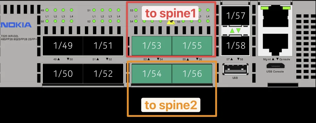
To support the non-sequential allocation shown above, set interfaceIndexIncrement: 2 to increment the interface index by 2 at each iteration. The iteration starts at the interface start index and continues until the number of interfaces per node pair is reached. The next node pair starts at the next lowest non-occupied interface index.
To define the port allocation pattern as shown in the picture above, the following link group definition can be used:
interSwitchLinkGroups:
  - name: leaf-spine
    template: leaf-spine-isl
    interfacesPerNodePair: 2
    localNodes:
      nodeSelectors:
        - eda.nokia.com/role=leaf
      interfaceStartIndex: "1-53"
      interfaceIndexIncrement: 2
    remoteNodes:
      nodeSelectors:
        - eda.nokia.com/role=spine
The workflow selects the local nodes matched by the nodeSelectors and picks the first interface index 1-53 as instructed by the interfaceStartIndex value. Based on the interfacesPerNodePair: 2 value, the workflow must allocate two interfaces between each local-remote node pair. The interfaceIndexIncrement: 2 value instructs the workflow to increment the interface index by 2 at each iteration. The first interface is allocated at index 1-53, the second at index 1-55. The two interfaces are allocated between the selected local-remote node pair.
The workflow continues and picks the next local-remote node pair and selects the next available interface index starting from 1-53. Since 1-53 is already occupied by the first interface, the workflow picks the next available interface index - 1-54 and follows the same pattern of allocating two interfaces with the increment of 2 - 1-54 and 1-56.
This is how interfaces 1-53 and 1-55 are allocated between leaf1 and spine1, and 1-54 and 1-56 are allocated between leaf1 and spine2.
Edge link groups#
An edge link group governs connectivity between edge nodes (typically leaves) and workload endpoints. It uses nodeSelectors to select local nodes and applies the count value to determine how many edge links to create.
By referencing an edge link template, the edge link group defines the type and properties of the edge links to create.
podTemplates:
  - name: leaf-spine-dcgw-pod
    edgeLinkGroups:
      - name: compute
        template: compute
        localNodes:
          nodeSelectors:
            - eda.nokia.com/role=leaf
        count: 10
The edge link count governs the number of edge links to create. When the referenced edge link template is of type ESLAG, the count specifies the number of multihomed interfaces to create. In the preceding example, count: 10 creates 10 multihomed interfaces, resulting in 10 servers that are each connected to a pair of leaves.
Link and interface names#
The workflow generates TopoLink and Interface resources based on the defined link groups. The names of these resources differ based on the link group type and can be customized using the linkName and interfaceName fields in the respective link group.
Inter-switch link group#
The linkName for the inter-switch link group defaults to the following template:
where:
.podName- the name of the pod where this group is instantiated.groupName- the name of the inter-switch link group.linkType- the type of the inter-switch link. Empty for regular ISL links, alagfor LAG ISL links..linkIndex- the index of the inter-switch link in this group. Starts at 1.
For the 3-tier topology example, the generated inter-switch link names from the leaf-spine link group are:
pod1-leaf-spine-1pod1-leaf-spine-2- and so on...
The linkName template can also reference pod-level variables by key and access the TopoLink .spec.links list through the .Links variable. For example, you can instruct the workflow to create inter-switch link names with full interface names for better readability:
You access the Link objects through the .Links variable, which contains the local and remote links for the current TopoLink.
interSwitchLinkGroups:
  - name: leaf-spine
    template: leaf-spine-isl
    interfacesPerNodePair: 2
    linkName: >-
      {{ (index .Links 0).Local.InterfaceResource }}
      --
      {{ (index .Links 0).Remote.InterfaceResource }}
      --
      {{.linkIndex}}
    localNodes:
      nodeSelectors:
        - eda.nokia.com/role=leaf
      interfaceStartIndex: "1-53"
      interfaceIndexIncrement: 2
    remoteNodes:
      nodeSelectors:
        - eda.nokia.com/role=spine
With the link name specified in the ISL group as shown above, the resulting TopoLink resources are named like this:
pod1-leaf01-ethernet-1-53--pod1-spine01-ethernet-1-1--1pod1-leaf01-ethernet-1-54--pod1-spine01-ethernet-1-2--2
Note that the interface resource value accessed through {{ (index .Links 0).Local.InterfaceResource }} already contains the pod and node names.
Each TopoLink resource contains the referenced nodes and interface, for example:
pod1-leaf-spine-1apiVersion: core.eda.nokia.com/v1
kind: TopoLink
metadata:
labels:
eda.nokia.com/link-type: interSwitch
eda.nokia.com/pod: pod1
eda.nokia.com/role: interSwitch
name: pod1-leaf-spine-1
namespace: eda
spec:
  links:
    - local:
        interface: ethernet-1-53
        interfaceResource: pod1-leaf01-ethernet-1-53
        node: pod1-leaf01
      remote:
        interface: ethernet-1-1
        interfaceResource: pod1-spine01-ethernet-1-1
        node: pod1-spine01
      speed: 100G
      type: interSwitch
The interfaceName field in the inter-switch link group defines the name of the Interface resource that the TopoLink resource references.
Its default value depends on the link type and is defined as follows:
where:
.nodeName- node name as defined in the node group definition..interfaceIndex- the interface index withethernet-prefix stripped (for example,1-53forethernet-1-53)..podName- the name of the pod where this group is instantiated..groupName- the name of the inter-switch link group..side- the side of the link that this interface is defined on. Either "local" or "remote"..linkIndex- the index of the link that this interface is part of. Starts at 1.
You can further customize the interface name using the following variables:
- pod level variables referenced by key.
.Linksvariable - a list of local and remote links the current interface is part of..Membersvariable - a list of member interfaces (as seen in theInterfaceresource) that the link consists of.
Edge link group#
Links and interfaces in the edge link group can be customized similarly to the inter-switch link group, with the following differences:
- The
.linkTypevariable resolves toeslagfor ESLAG links,lagfor LAG links, and an empty value for regular edge links. - default interface template is
{{.podName}}-{{.groupName}}{{if .linkType}}-{{.linkType}}{{end}}-{{.linkIndex}}-{{.side}}e.g.pod1-compute-eslag-8-local
Pods#
The pods section instantiates pod templates. A pod is a named instance of a reusable pod template.
The only required fields are the name and the podTemplate reference that selects the pod template to instantiate. Because pods is a list of pod instances, you can scale the data center by adding multiple pods.
Pod variables#
Pod variables can be defined at the pod level and used anywhere in the workflow that supports template syntax. See the nodeName examples above for facility or country code usage.
Values must be lower case and alphanumeric only.
To access the variables in the workflow, use the {{.variableKey}} syntax.
Workflow operations#
Operations that are supported by the Network Topology workflow are also supported by the Fabric Topology workflow.
Workflow call chain#
When a FabricTopology resource runs, it computes the inputs for the child Network Topology workflow. In the workflow UI, the final step runs the Network Topology workflow.
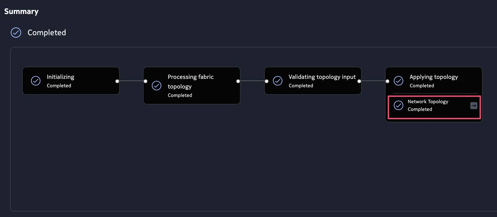
You can open the Network Topology workflow resource, copy its YAML, and modify it to fine-tune the topology and run it directly as the Network Topology workflow.
Digital-twin (simulation) topology#
The Fabric Topology workflow currently uses TestMan pods to simulate workloads. It does not support other simulation pod types or custom simulation-topology wiring.
Examples#
The following examples demonstrate how to use the Fabric Topology workflow to create different data center topologies.
The topology examples deliberately use fewer nodes to ensure they fit within the limits of a small compute cluster. Change the node group
countvalues to scale the topology to your needs.
You can change the node profile in the node templates to choose the desired hardware platform, software version, or both.
Two-tier topology#
- tiers: leaf and spine
- leaf: 7220 IXR-D2L
- spine: 7220 IXR-D3L
- access: multihomed ESLAG connections from leaves to workloads with two leaves per server
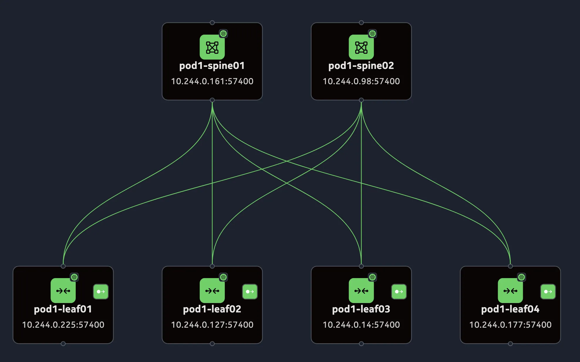
Two-tier topology workflow spec
apiVersion: fabrics.eda.nokia.com/v1
kind: FabricTopology
metadata:
name: 2tier-200g
namespace: eda
spec:
operation: Reconcile
#########################
#### Node Templates #####
#########################
nodeTemplates:
- name: leaf
nodeProfile: srlinux-ghcr-26.3.1
platform: 7220 IXR-D2L
- name: spine
nodeProfile: srlinux-ghcr-26.3.1
platform: 7220 IXR-D3L
#########################
## Edge Link Templates ##
#########################
edgeLinkTemplates:
- name: compute
type: ESLAG
encapType: Dot1q
nodesInLAG: 2
#################################
## Inter Switch Link Templates ##
#################################
interSwitchLinkTemplates:
- name: d3l-leaf-spine-isl
type: InterSwitch
speed: 100G
encapType: "Null"
#########################
#### Pod Templates #####
#########################
podTemplates:
- name: leaf-spine-pod
nodeGroups:
- name: leaf
nodeName: '{{.podName}}-leaf{{ printf "%02d" .nodeIndex }}'
nodeTemplate: leaf
count: 4
- name: spine
nodeName: '{{.podName}}-spine{{printf "%02d" .nodeIndex}}'
nodeTemplate: spine
count: 2
##############################
## Inter Switch Link Groups ##
##############################
interSwitchLinkGroups:
- name: leaf-spine
template: d3l-leaf-spine-isl
interfacesPerNodePair: 2
localNodes:
nodeSelectors:
- eda.nokia.com/role=leaf
interfaceStartIndex: "1-53"
remoteNodes:
nodeSelectors:
- eda.nokia.com/role=spine
interfaceStartIndex: "1-1"
##############################
###### Edge Link Groups ######
##############################
edgeLinkGroups:
- name: compute
template: compute
localNodes:
nodeSelectors:
- eda.nokia.com/role=leaf
count: 30
###############
#### Pods #####
###############
pods:
- name: pod1
podTemplate: leaf-spine-pod
Three-tier topology#
- tiers: leaf, spine, and DC gateway
- leaf: 7220 IXR-D2L
- spine: 7220 IXR-D3L
- DC gateway: 7750 SR-1s with c1-100g connectors
- access: direct individual interfaces to the workload
This topology example has 12 leaf nodes. If you use a small compute cluster, consider reducing this number.
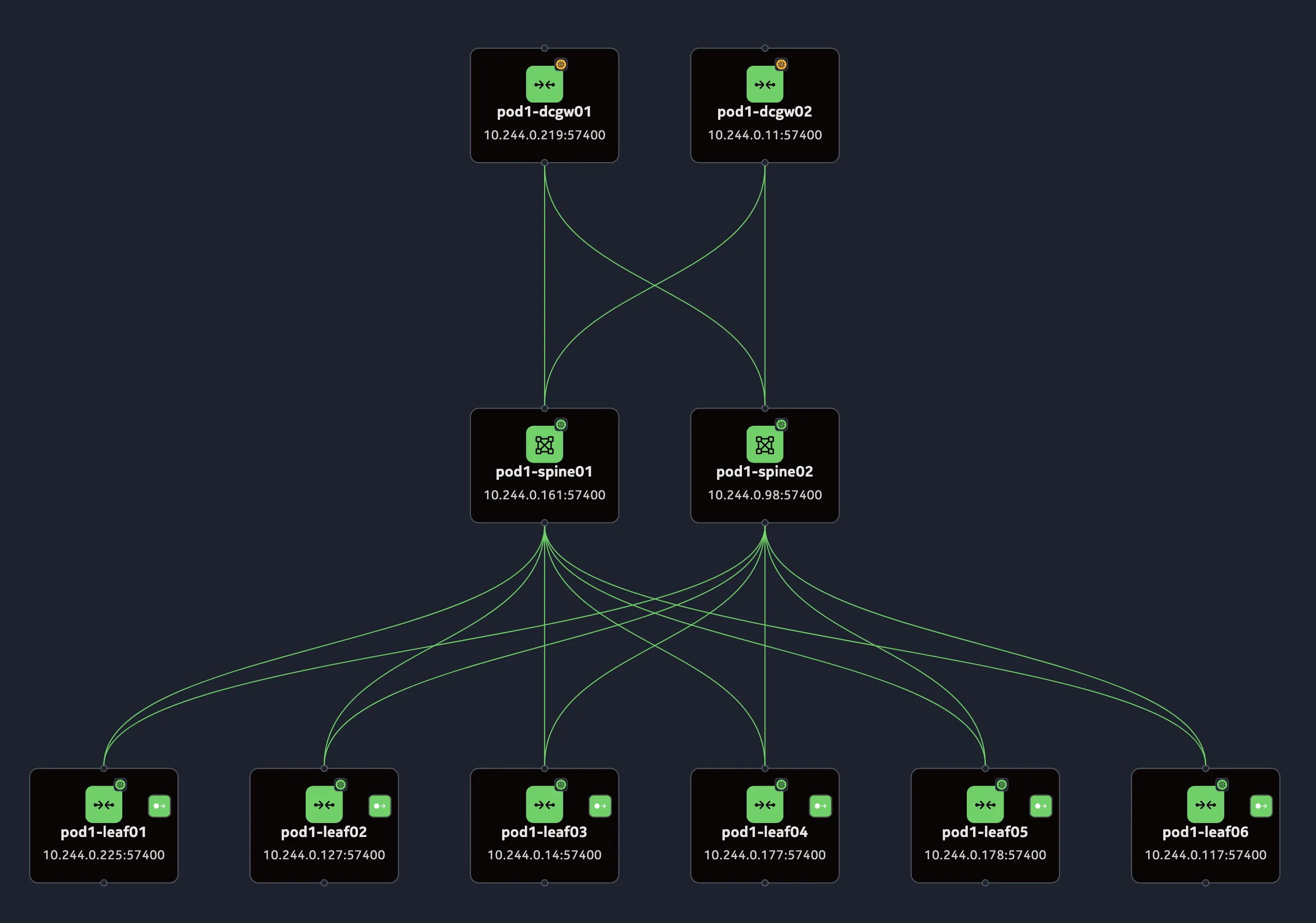
Three-tier topology workflow spec
apiVersion: fabrics.eda.nokia.com/v1
kind: FabricTopology
metadata:
name: 3tier-200g-12l2s2dcgw-1
namespace: eda
spec:
#########################
#### Node Templates #####
#########################
nodeTemplates:
- name: leaf
nodeProfile: srlinux-ghcr-26.3.1
platform: 7220 IXR-D2L
# labels:
- name: spine
nodeProfile: srlinux-ghcr-26.3.1
platform: 7220 IXR-D3L
- name: dcgw
nodeProfile: srsim-int-26.3.r1
platform: 7750 SR-1s
components:
- kind: lineCard
slot: "1"
type: xcm-1s
- kind: powerShelf
slot: "1"
type: ps-a4-shelf-dc
- kind: powerModule
slot: 1-{{1..4}}
type: ps-a-dc-6000
- kind: mda
slot: 1-a
type: s18-100gb-qsfp28
- kind: connector
slot: 1-a-{{1..18}}
type: c1-100g
#################################
## Inter Switch Link Templates ##
#################################
interSwitchLinkTemplates:
- name: leaf-spine-isl
type: InterSwitch
speed: 100G
encapType: "Null"
- name: spine-dcgw-isl
type: InterSwitch
speed: 100G
encapType: "Null"
#########################
## Edge Link Templates ##
#########################
edgeLinkTemplates:
- name: compute
type: ESLAG
encapType: Dot1q
nodesInLAG: 2
#########################
#### Pod Templates #####
#########################
podTemplates:
- name: leaf-spine-dcgw-pod
nodeGroups:
- name: leaf
nodeName: '{{.podName}}-{{.nodeGroupName}}{{ printf "%02d" .nodeIndex }}'
nodeTemplate: leaf
count: 12
- name: spine
nodeName: '{{.podName}}-{{.nodeGroupName}}{{printf "%02d" .nodeIndex}}'
nodeTemplate: spine
count: 2
- name: dcgw
nodeName: '{{.podName}}-{{.nodeGroupName}}{{printf "%02d" .nodeIndex}}'
nodeTemplate: dcgw
count: 2
##############################
## Inter Switch Link Groups ##
##############################
interSwitchLinkGroups:
- name: leaf-spine
template: leaf-spine-isl
interfacesPerNodePair: 2
localNodes:
nodeSelectors:
- eda.nokia.com/role=leaf
interfaceStartIndex: "1-53"
interfaceIndexIncrement: 2
remoteNodes:
nodeSelectors:
- eda.nokia.com/role=spine
- name: spine-dcgw
template: spine-dcgw-isl
interfacesPerNodePair: 2
localNodes:
nodeSelectors:
- eda.nokia.com/role=spine
interfaceStartIndex: "1-25"
remoteNodes:
nodeSelectors:
- eda.nokia.com/role=dcgw
interfaceStartIndex: "1-a-{{1..}}-1"
##############################
###### Edge Link Groups ######
##############################
edgeLinkGroups:
- name: compute
template: compute
localNodes:
nodeSelectors:
- eda.nokia.com/role=leaf
count: 10
operation: Reconcile
###############
#### Pods #####
###############
pods:
  - name: pod1
    podTemplate: leaf-spine-dcgw-pod
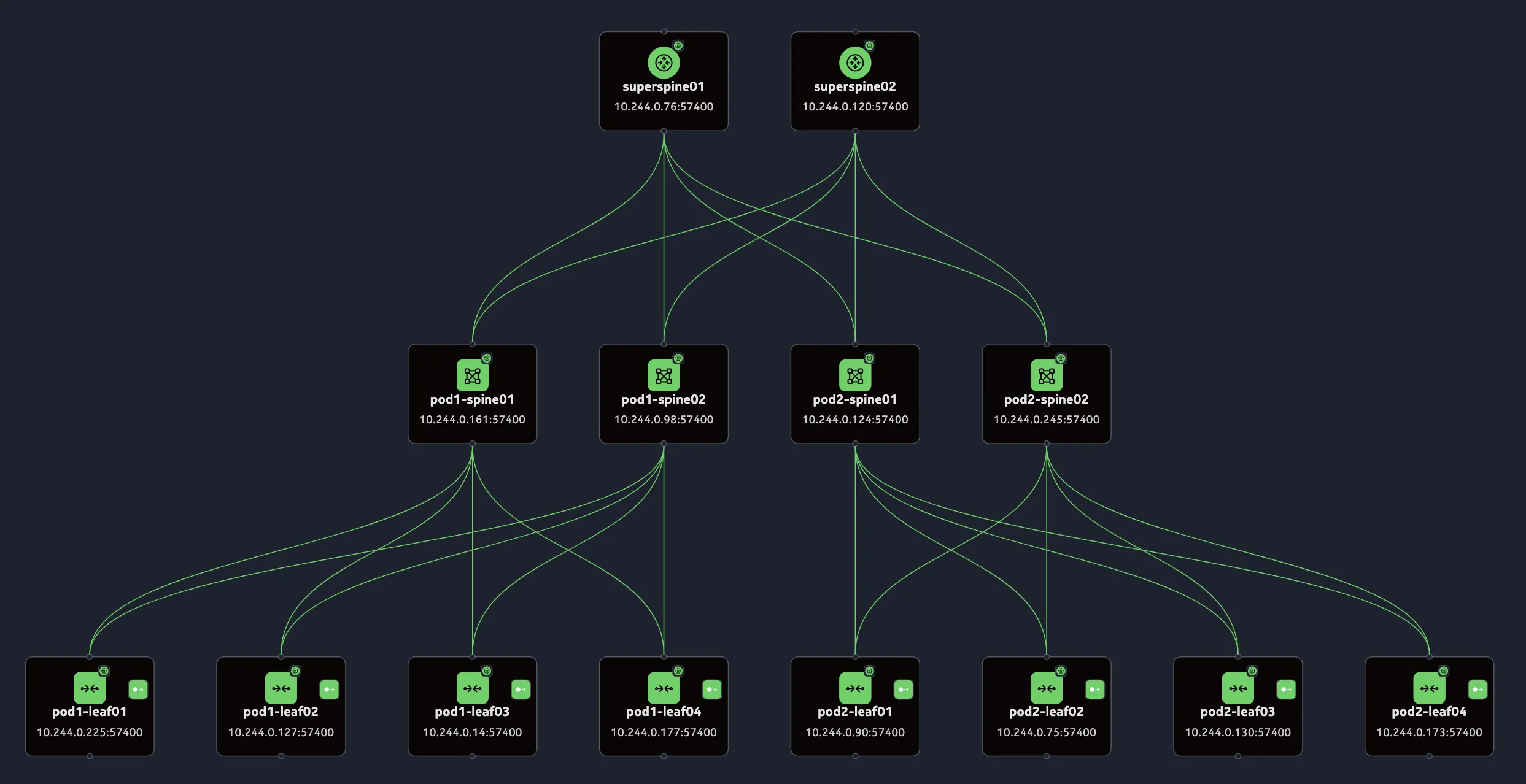
Three-tier multi-pod topology#
- tiers: leaf, spine, and superspine
- leaf: 7220 IXR-D2L
- spine: 7220 IXR-D3L
- superspine: 7220 IXR-D3L
- access: direct individual interfaces to the workload
In this topology, the leaf-spine pods (pod1 and pod2) are interconnected by a superspine pod. The superspine pod defines the superspine nodes and the inter-switch links that connect them to the nodes in all leaf-spine pods.
Three-tier multi-pod topology workflow spec
apiVersion: fabrics.eda.nokia.com/v1
kind: FabricTopology
metadata:
  name: 3tier-200g-superspine
  namespace: eda
spec:
  #########################
  #### Node Templates #####
  #########################
  nodeTemplates:
    - name: leaf
      nodeProfile: srlinux-ghcr-26.3.1
      platform: 7220 IXR-D2L
    - name: spine
      nodeProfile: srlinux-ghcr-26.3.1
      platform: 7220 IXR-D3L
    - name: superspine
      nodeProfile: srlinux-ghcr-26.3.1
      platform: 7220 IXR-D3L

  #########################
  ## Edge Link Templates ##
  #########################
  edgeLinkTemplates:
    - name: compute
      type: ESLAG
      encapType: Dot1q
      nodesInLAG: 2

  #################################
  ## Inter Switch Link Templates ##
  #################################
  interSwitchLinkTemplates:
    - name: leaf-spine-isl
      type: InterSwitch
      speed: 100G
      encapType: "Null"
    - name: spine-superspine-isl
      type: InterSwitch
      speed: 100G
      encapType: "Null"

  podTemplates:
    #############################
    ## 3-tier Pod Templates    ##
    #############################
    ## Leaf-Spine Pod Template
    - name: leaf-spine-pod
      nodeGroups:
        - name: leaf
          nodeName: '{{.podName}}-leaf{{ printf "%02d" .nodeIndex }}'
          nodeTemplate: leaf
          count: 4
        - name: spine
          nodeName: '{{.podName}}-spine{{printf "%02d" .nodeIndex}}'
          nodeTemplate: spine
          count: 2
      ##############################
      ## Inter Switch Link Groups ##
      ##############################
      interSwitchLinkGroups:
        - name: leaf-spine
          template: leaf-spine-isl
          interfacesPerNodePair: 2
          localNodes:
            nodeSelectors:
              - eda.nokia.com/role=leaf
            interfaceStartIndex: "1-53"
          remoteNodes:
            nodeSelectors:
              - eda.nokia.com/role=spine
      ##############################
      ###### Edge Link Groups ######
      ##############################
      edgeLinkGroups:
        - name: compute
          template: compute
          localNodes:
            nodeSelectors:
              - eda.nokia.com/role=leaf
          count: 10

    ## Superspine Pod Template
    - name: superspine-pod
      nodeGroups:
        - name: superspine
          nodeName: 'superspine{{printf "%02d" .nodeIndex}}'
          nodeTemplate: superspine
          count: 2
      interSwitchLinkGroups:
        - name: spine-superspine
          template: spine-superspine-isl
          interfacesPerNodePair: 2
          localNodes:
            nodeSelectors:
              - eda.nokia.com/role=spine
            interfaceStartIndex: "1-29"
          remoteNodes:
            nodeSelectors:
              - eda.nokia.com/role=superspine
  operation: Reconcile
  ###############
  #### Pods #####
  ###############
  pods:
    - name: pod1
      podTemplate: leaf-spine-pod
    - name: pod2
      podTemplate: leaf-spine-pod
    - name: superspine-pod
      podTemplate: superspine-pod